


ASUS P5WDG2-WSASUS P5WDG2-WS
ASUS P5WDG2-WSASUS P5WDG2-WS
ASUS P5WDG2-WS
2-412-41
2-412-41
2-41
13.13.
13.13.
13.
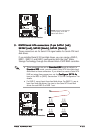
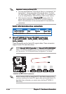
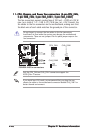
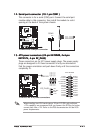
ATX power connectors (24-pin EATXPWR, ATX power connectors (24-pin EATXPWR,
ATX power connectors (24-pin EATXPWR, ATX power connectors (24-pin EATXPWR,
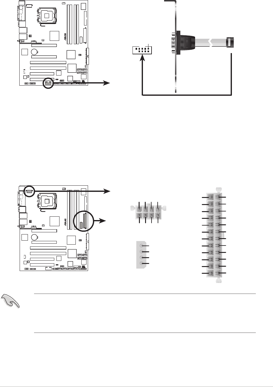
ATX power connectors (24-pin EATXPWR,
2x42x4
2x42x4
2x4
-pin-pin
-pin-pin
-pin
EE
EE
E
ATX12VATX12V
ATX12VATX12V
ATX12V
, 4-pin EZ_PLUG, 4-pin EZ_PLUG
, 4-pin EZ_PLUG, 4-pin EZ_PLUG
, 4-pin EZ_PLUG
))
))
)
These connectors are for ATX power supply plugs. The power supply
plugs are designed to fit these connectors in only one orientation.
Find the proper orientation and push down firmly until the connectors
completely fit.
When installing two VGA cards using a 20-pin ATX PSU with sufficient
+12V capability, we recommend that you connect the EZ Plug for better
current path from +12V. Refer to the PSU documentation for dual VGA
power requirements.
12.12.
12.12.
12.
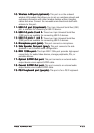
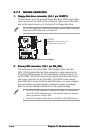
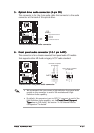
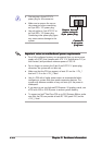
Serial port connector (10-1 pin COM1)Serial port connector (10-1 pin COM1)
Serial port connector (10-1 pin COM1)Serial port connector (10-1 pin COM1)
Serial port connector (10-1 pin COM1)
This connector is for a serial (COM) port. Connect the serial port
module cable to this connector, then install the module to a slot
opening at the back of the system chassis.
P5WDG2-WS
®
P5WDG2-WS COM port connector
PIN 1
COM1
P5WDG2-WS
®
P5WDG2-WS ATX power connectors
EATXPWR
EATX12V
EZ_PLUG
+5V
EZ_DET
GND
+12V
+3 Volts
+3 Volts
Ground
+5 Volts
+5 Volts
Ground
Ground
Power OK
+5V Standby
+12 Volts
-5 Volts
+5 Volts
+3 Volts
-12 Volt
s
Ground
Ground
Ground
PSON#
Ground
+5 Volts
+12 Volts
+3 Volts
+5 Volts
Ground
GND +12V DC
GND
+12V DC
GND
+12V DC
GND
+12V DC