


1-7Chapter 1: Product introduction
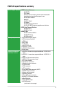
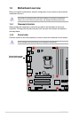
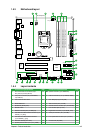
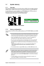
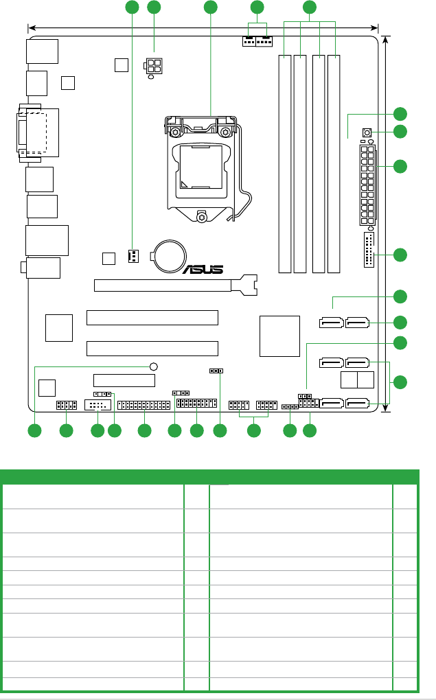
1.5.3 Motherboard layout
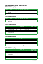
1.5.4 Layout contents
Connectors/Jumpers/Slots/LED Page Connectors/Jumpers/Slots/LED Page
1. CPU and chassis fan connectors (4-pin
CPU_FAN, 3-pin CHA_FAN1/2)
1-27 12. Speaker connector (4-pin SPEAKER) 1-28
2. ATX power connectors (24-pin EATXPWR,
4-pin ATX12V)
1-26 13. USB 2.0 connectors (10-1 pin USB56, USB78) 1-30
3. Intel
®
LGA1155 CPU socket 1-8 14. Intel
®
ME jumper (3-pin DIS_ME) 1-21
4. DDR3 DIMM slots 1-13 15. TPM connector (20-1 pin TPM) 1-31
5. DRAM LED (DRAM_LED) 1-33 16. Chassis intrusion connector (4-1 pin CHASSIS) 1-26
6. MemOK! switch 1-32 17. LPT connector (26-1 pin LPT) 1-27
7. USB 3.0 connector (20-1 pin USB3_34) 1-30 18. Digital audio connector (4-1 pin SPDIF_OUT) 1-25
8. Intel
®
B75 Serial ATA 3.0Gb/s connectors (7-pin
SATA3G_1~5 [blue])
1-29 19. Serial port connector (10-1 pin COM1) 1-31
9. Intel
®
B75 Serial ATA 6.0Gb/s connectors
(7-pin SATA6G_1 [gray])
1-29 20. Front panel audio connector (10-1 pin AAFP) 1-25
10. Clear RTC RAM (3-pin CLRTC) 1-22 21. Onboard LED (SB_PWR) 1-33
11. System panel connector (10-1 pin F_PANEL) 1-28
P8B75-M
PCIEX16
PCI1
PCI2
PCIEX4_1
AAFP
EATXPWR
CPU_FAN
CHA_FAN2
CHA_FAN1
Lithium Cell
CMOS Power
Super
I/O
VIA
VT1708S
EPU
ASM
1442
KBMS
HDMI
64Mb
BIOS
64Mb
BIOS
SB_PWR
CLRTC
DIS_ME
22.6cm(8.9in)
24.4cm(9.6in)
Intel
®
B75
DDR3 DIMM_B1 (64bit, 240-pin module)
DDR3 DIMM_B2 (64bit, 240-pin module)
DDR3 DIMM_A1 (64bit, 240-pin module)
DDR3 DIMM_A2 (64bit, 240-pin module)
SATA3G_5 SATA3G_4
SATA3G_3 SATA3G_2
SATA3G_1 SATA6G_1
AUDIO
USB3_12
USB34
LAN_USB12
SPDIF_OUT
LPT
DVI_VGA
DRAM_LED
MemOK!
LGA1155
USB3_34
F_PANEL
SPEAKER
USB56USB78
TPM
COM1
C
H
A
S
S
IS
RTL
8111F
ATX12V
1 12 3 4
1113 1215161719 1820
6
2
7
8
9
8
10
5
1421