


1-27Chapter 1: Product introduction
Do not forget to connect the fan cables to the fan connectors. Insufcient air ow inside the
system may damage the motherboard components. These are not jumpers! Do not place
jumper caps on the fan connectors!
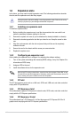
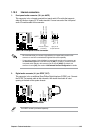
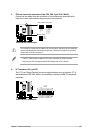
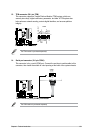
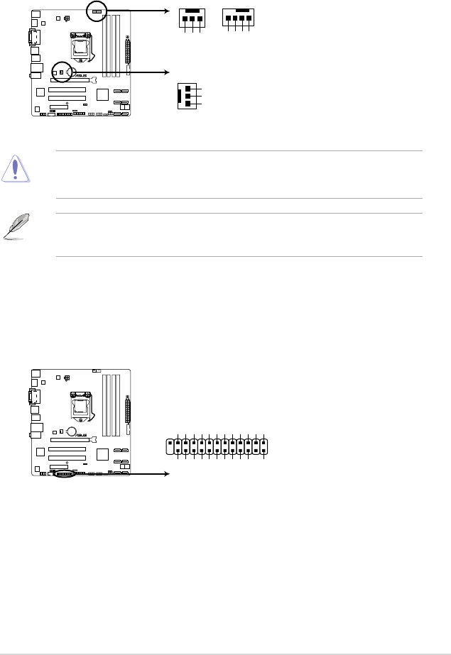
5. CPU and chassis fan connectors (4-pin CPU_FAN, 3-pin CHA_FAN1/2)
Connect the fan cables to the fan connectors on the motherboard, ensuring that the
black wire of each cable matches the ground pin of the connector.
• The CPU_FAN connector supports a CPU fan of maximum 2A (24 W) fan power.
• Only the 4-pin CPU fan supports the ASUS FanXpert and Q-Fan 2 feature.
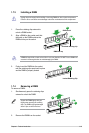
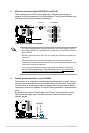
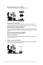
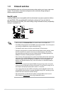
6. LPT connector (26-1 pin LPT)
The LPT (Line Printing Terminal) connector supports devices such as a printer. LPT is
standardized as IEEE 1284, which is the parallel port interface on IBM PC-compatible
computers.
CHA_FAN1
CHA_FAN2
P8B75-M
P8B75-M fan connectors
GND
+12V
Rotation
Rotation
+12V
GND
CPU_FAN
CPU FAN PWM
CPU FAN IN
CPU FAN PWR
GND
P8B75-M
P8B75-M LPT connector
LPT
PIN 1
SLCT
PE
BUSY
ACK#
PD7
PD6
PD5
PD4
PD3
PD2
PD1
PD0
STB#
GND
GND
GND
GND
GND
GND
GND
GND
SLIN#
INIT#
ERR#
AFD