


ASUS P8Z77-M
1-22
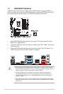
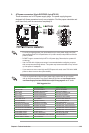
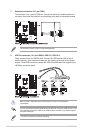
1.10.2 Internal connectors
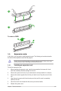
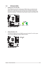
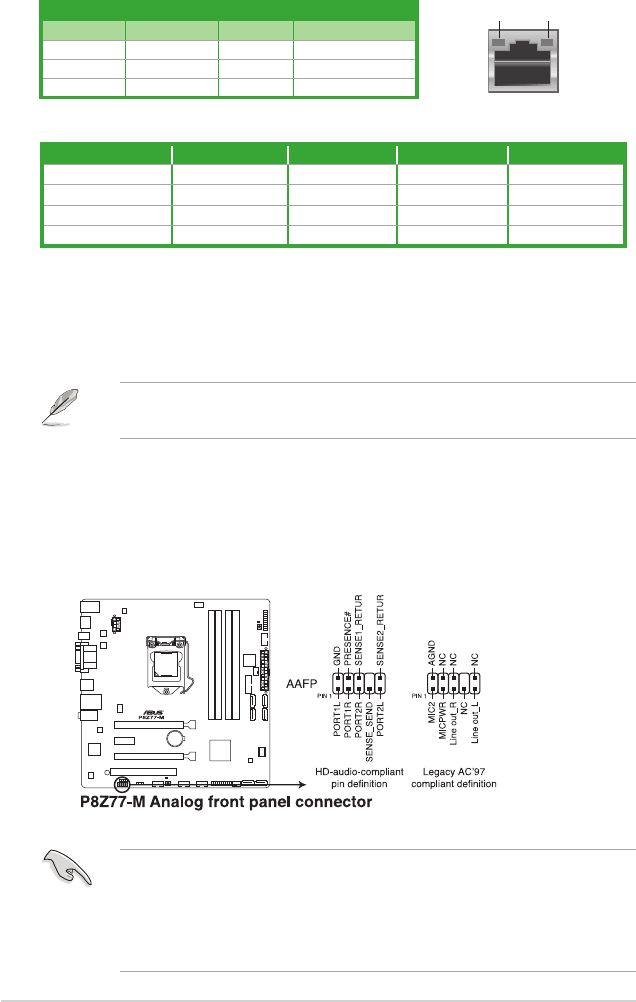
1. Front panel audio connector (10-1 pin AAFP)
This connector is for a chassis-mounted front panel audio I/O module that supports
either HD Audio or legacy AC`97 audio standard. Connect one end of the front panel
audio I/O module cable to this connector.
• We recommend that you connect a high-denition front panel audio module to this
connector to avail of the motherboard’s high-denition audio capability.
• If you want to connect a high-denition front panel audio module to this connector, set
the Front Panel Type item in the BIOS setup to [HD]. If you want to connect an AC'97
front panel audio module to this connector, set the item to [AC97]. By default, this
connector is set to [HD]. See section 2.5.6 Onboard Devices Conguration for details.
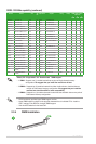
Port Headset 2-channel 4-channel 6-channel 8-channel
Light Blue (Rear panel) Line In Rear Speaker Out Rear Speaker Out Rear Speaker Out
Lime (Rear panel) Line Out Front Speaker Out Front Speaker Out Front Speaker Out
Pink (Rear panel) Mic In Mic In Bass/ Center Bass/ Center
Lime (Front panel) – – – Front Speaker Out
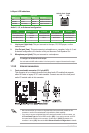
Audio 2, 4, 6, or 8-channel conguration
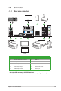
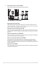
LAN port
Speed
LED
Activity Link
LED
Activity/Link LED Speed LED
Status Description Status Description
OFF No link OFF 10Mbps connection
ORANGE Linked ORANGE 100Mbps connection
BLINKING Data activity GREEN 1Gbps connection
LAN port LED indications
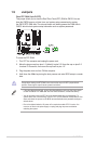
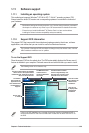
To congure an 8-channel audio output:
Use a chassis with HD audio module in the front panel to support 8-channel audio output.
1. Line In port (light blue). This port connects to the tape, CD, DVD player, or other
audio sources.
2. Line Out port (lime). This port connects to a headphone or a speaker. In the 4, 6, and
8-channel congurations, the function of this port becomes Front Speaker Out.
3. Microphone port (pink). This port connects to a microphone.