


1-22
Chapter 1: Product introduction
Chapter 1
Chapter 1
Chapter 1
Chapter 1
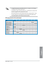
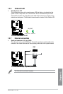
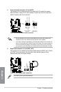
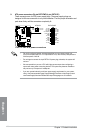
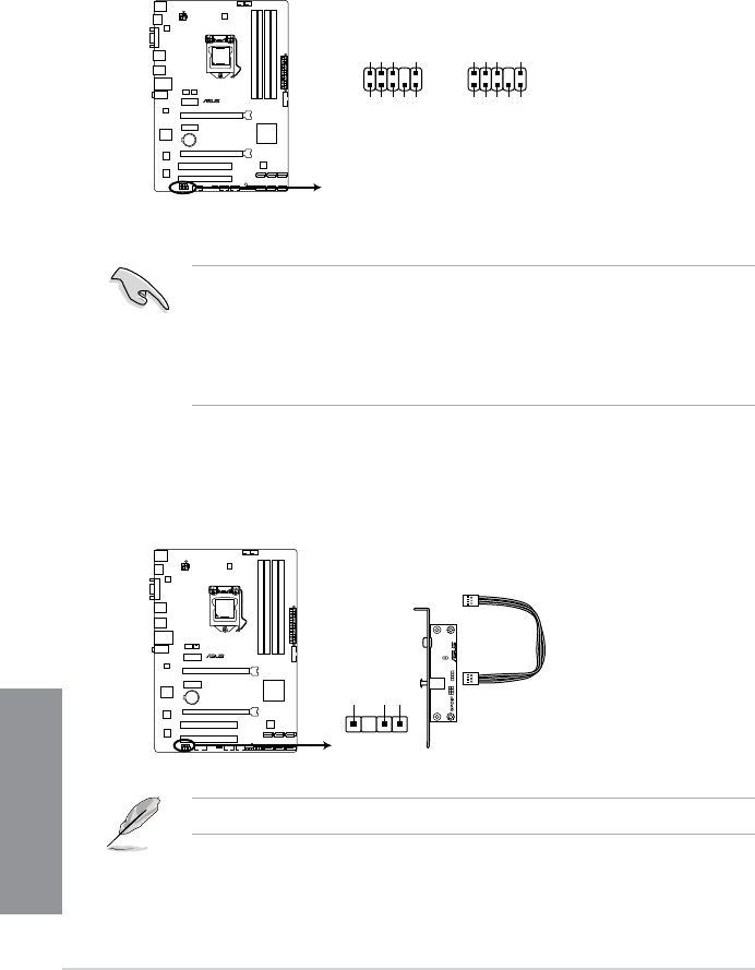
4. Front panel audio connector (10-1 pin AAFP)
This connector is for a chassis-mounted front panel audio I/O module that supports
either HD Audio or legacy AC`97 audio standard. Connect one end of the front panel
audio I/O module cable to this connector.
• We recommend that you connect a high-denition front panel audio module to this
connector to avail of the motherboard’s high-denition audio capability.
• If you want to connect a high-denition front panel audio module to this connector, set
the Front Panel Select item in the BIOS setup to [HD Audio]; if you want to connect an
AC'97 front panel audio module to this connector, set the item to [AC 97]. By default,
this connector is set to [HD]. Refer to 3.5.6 Onboard Devices Conguration for details.
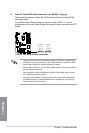
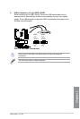
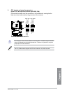
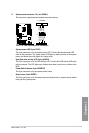
5. Digital audio connector (4-1 pin SPDIF_OUT)
This connector is for an additional Sony/Philips Digital Interface (S/PDIF) port. Connect
the S/PDIF Out module cable to this connector, then install the module to a slot
opening at the back of the system chassis.
P8Z77-V LX2
P8Z77-V LX2 Front panel audio connector
AAFP
PIN 1
AGND
NC
SENSE1_RETUR
SENSE2_RETUR
PORT1 L
PORT1 R
PORT2 R
SENSE_SEND
PORT2 L
HD-audio-compliant
pin definition
PIN 1
AGND
NC
NC
NC
MIC2
MICPWR
Line out_R
NC
Line out_L
Legacy AC’97
compliant definition
The S/PDIF module is purchased separately.
SPDIF_OUT
+5V
SPDIFOUT
GND
P8Z77-V LX2
P8Z77-V LX2 Digital audio connector