


ASUS P/I-P55TVP4 User's Manual 13
III. INSTALLATION
(DRAM Memory)
III. INSTALLATION
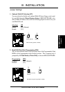
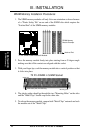
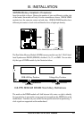
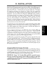
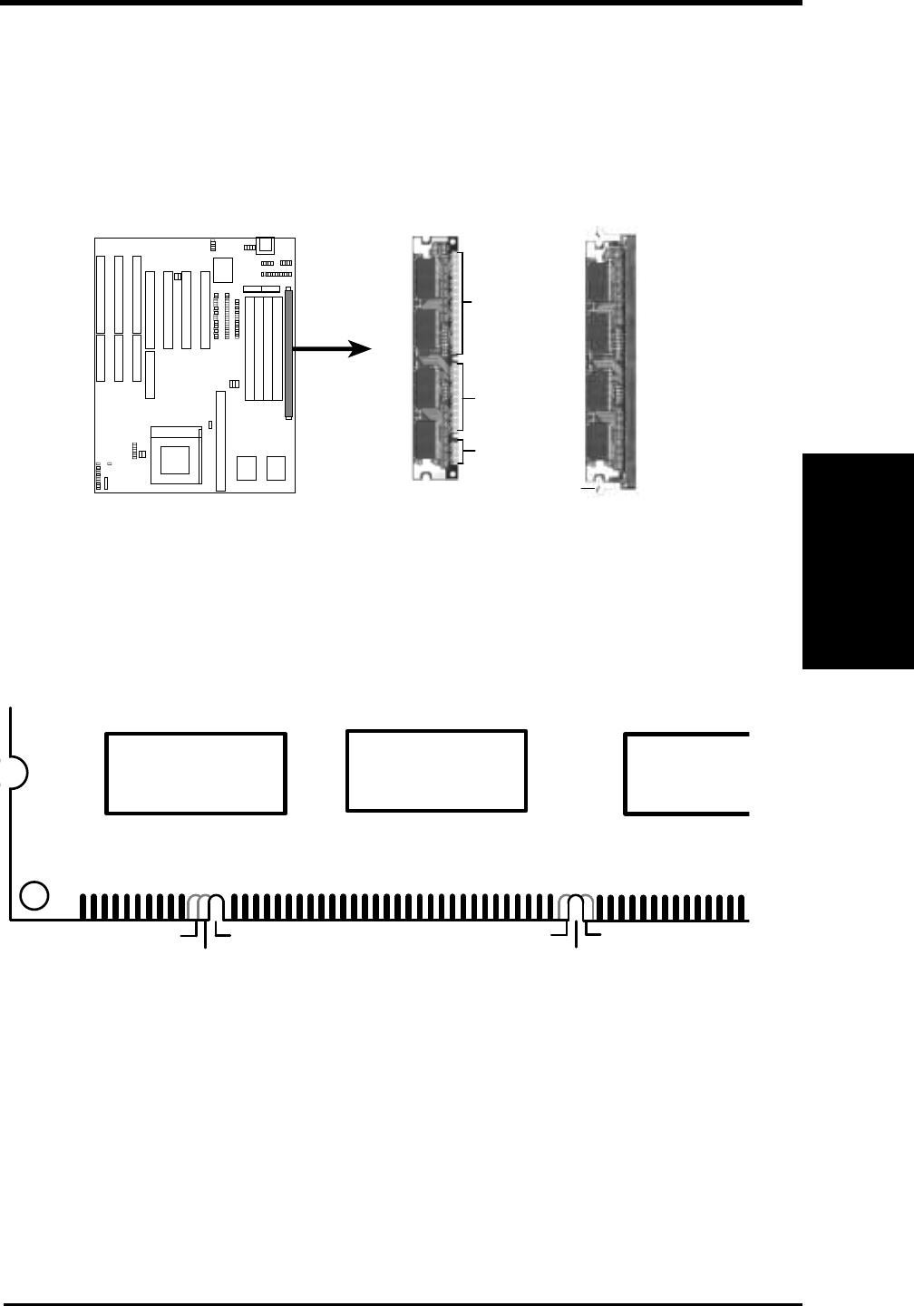
SDRAM Memory Installation Procedures:
Insert the module as shown. Because the number of pins are different on either side
of the breaks, the module will only fit in the orientation as shown. DRAM SIMM
modules have the same pin contact on both sides. SDRAM DIMM modules have
different pint contact on each side and therefore have a higher pin density.
168 Pin DIMM Socket & SDRAM Module
88 Pins
60 Pins
20 Pins
Lock
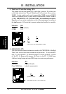
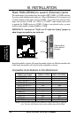
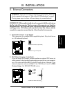
The Dual Inline Memory Module (DIMM) memory module must be 3.3Volt Unbuf-
fered Synchronous DRAM (SDRAM) of either 8, 16, 32, or 64MB. You can iden-
tify the type of DIMM module by the illustration below:
Unbuffered
RFU
Buffered
Reserved
3.3V
5.0V
168-PIN SDRAM DIMM Notch Key Definitions
SDRAM Key Position
Voltage Key Position
The notch on the DIMM module will shift between left, center, or right to identify
the type and also to prevent the wrong type to be inserted into the DIMM slot on the
motherboard. You must ask your retailer for the specifications before purchasing. 4
clock signals are supported on this motherboard.