


ASUS P/I-P55TVP4 User's Manual20
III. INSTALLATION
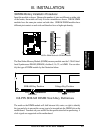
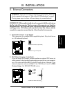
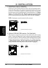
3. Parallel Printer Connector (26 Pin Block)
Connection for the included parallel port ribbon cable with mounting bracket.
Connect the ribbon cable to this connection and mount the bracket to the case on
an open slot. It will then be available for a parallel printer cable. You can enable
the parallel port and choose the IRQ through "Onboard Parallel Port" in Chipset
Features of the BIOS SOFTWARE. (Pin 26 is removed to prevent inserting
in the wrong orientation when using ribbon cables with pin 26 plugged).
NOTE: Serial printers must be connected to the serial port.
Onboard Parallel (Printer) Connector
Pin 1
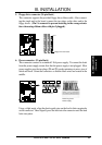
4. Serial port COM1 and COM2 connectors (Two 10-pin blocks)
These connectors support the provided serial port ribbon cables with mounting
bracket. Connect the ribbon cables to these connectors and mount the bracket to
the case on an open slot. The two serial ports on the mounting bracket will then
be used for pointing devices or other serial devices. See "Onboard Serial Port"
in Chipset Features Setup. (Pin 10 is removed to prevent inserting in the
wrong orientation when using ribbon cables with pin 10 plugged).
Onboard Serial Port Connectors
COM 1
COM 2
Pin 1
Pin 1
(Connectors)
III. INSTALLATION