


4 ASUS P/I-P55TVP4 User’s Manual
III. INSTALLATION
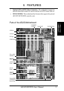
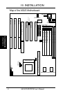
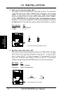
Map of the ASUS Motherboard
ISA Slot 3
ISA Slot 2
ISA Slot 1
PCI Slot 4 / MediaBus 2.0
PCI Slot 3
PCI Slot 2
PCI Slot 1
Super
Multi I/O
JP9
JP10
Block Program (Dis/En)
Multi I/O (En/Dis)
JP1
JP2
JP3
BUS FREQ
Board Power Input
P8
P9
Primary IDE
Secondary IDE
Universal Serial Bus
(Reserved for future use)
PS/2 Mouse
Floppy Drives
Keyboard
SIMM Socket 1 (Bank 0)
SIMM Socket 2 (Bank 0)
SIMM Socket 3 (Bank 1)
SIMM Socket 4 (Bank 1)
DIMM Socket 1 (Bank 2)
DIMM Socket 2 (Bank 3)
CPU ZIF Socket 7
JP4
L2 CACHE
256/512KB OnBoard L2 Cache
Pipelined Burst Level 2 Cache Expansion Slot
Infrared Con.
Case Conn (CON 1)
JP22
JP21
JP20
JP19
JP18
JP17
JP16
Vio/Vcore
JP5
JP6
BUS Ratio
JP7
RTC Clear
IDE LED
Parallel Port (Printer)
Serial Ports
COM 2
COM 1
(Map of Board)
III. INSTALLATION