


ASUS P/I-P55TVP4 User’s Manual 5
III. INSTALLATION
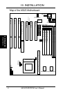
Jumpers
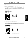
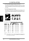
1) JP9 p. 7 Multi-I/O Selection (Enable/Disable)
2) JP10 p. 7 Flash ROM Boot Block Program (Disable/Enable)
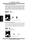
3) JP4 p. 8 Total Level 2 Cache Size Setting
4) JP7 p. 8 Real Time Clock RAM (Operation/Clear Data)
5) JP16-22 p. 9 CPU Voltage Selection
6) JP1, 2, 3 p. 10 CPU External Clock (BUS) Frequency Selection
7) JP5, JP6 p. 10 CPU:BUS Frequency Ratio
Expansion Slots
1) SIMM Sockets p. 11 72-Pin DRAM Memory Expansion Sockets
2) DIMM Sockets p. 13 168-Pin SDRAM Memory Expansion Sockets
3) Cache Expansion p. 14 Pipelined Burst SRAM Cache Module Socket
4) ZIF Socket 7 p. 15 Central Processing Unit (CPU) Socket
5) ISA Slots 1,2,3 p. 16 16-bit ISA Bus Expansion Slots
6) PCI Slots 1,2,3 p. 16 32-bit PCI Bus Expansion Slots
Connectors
1) KBCON p. 19 Keyboard Connector (5-pin Female)
2) PS2MOUSE p. 19 PS/2 Mouse Connector (6-pin Block)
3) PRINTER p. 20 Parallel (Printer) Port Connector (26-pin Block)
4) COM1, COM2 p. 20 Serial Port COM1 & COM2 (10-pin Blocks)
5) FLOPPY p. 21 Floppy Drive Connector (34-pin Block)
6) POWER p. 21 Motherboard Power Connector (12-pin Block)
7) Primary / Second IDE p. 22 Primary / Secondary IDE Connector (40-pin Blocks)
8) IDELED p. 22 IDE LED Activity Light
9) TB LED (CON1) p. 23 Turbo LED/Power LED (2-pins)
10) SMI (CON1) p. 23 SMI Switch Lead (2-pins)
11) RESET (CON1) p. 23 Reset Switch Lead (2-pins)
12) KEYLOCK (CON1) p. 23 Keyboard Lock Switch Lead (5-pins)
13) SPEAKER (CON1) p. 23 Speaker Output Connector (4-pins)
14) IR p. 24 Infrared Port Module Connector
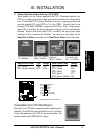
(Map of Board)
III. INSTALLATION