


ASUS SP97 / SP97-V User’s Manual 31
III. INSTALLATION
(Connectors)
III. INSTALLATION
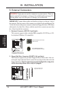
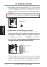
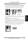
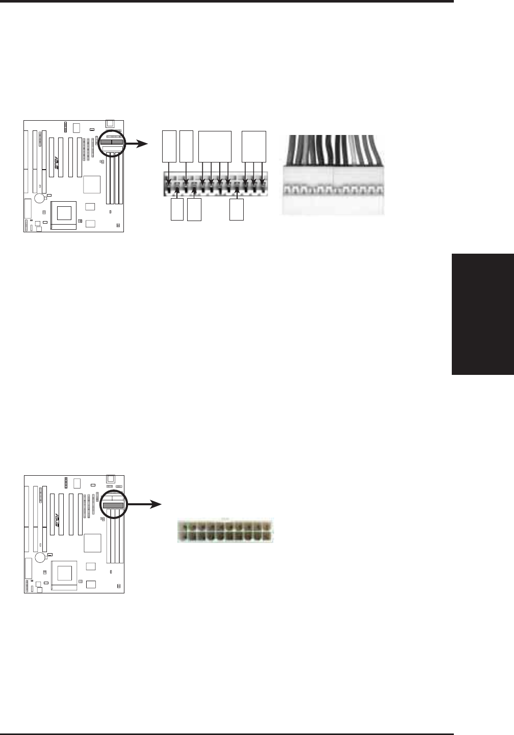
16. AT Power Supply Connector (POWER, 12-pin block)
This connector connects to a standard 5-volt power supply. To connect the leads
from the power supply, ensure first that the power supply is not plugged. Most
power supplies provide two plugs (P8 and P9), each containing six wires, two of
which are black. Orient the connectors so that the black wires are together.
AT Power Connector
Power Plugs from
Power Supply
P9
P8
ORG
RED
YLW
BLU
BLK
BLK
BLK
BLK
WHT
RED
RED
RED
Power Connector
on Motherboard
PG
+12V
GND
-5V
-12V
+5V
+5V
R
Using a slight angle, align the plastic guide pins on the lead to their receptacles
on the connector. Once aligned, press the lead onto the connector until the lead
locks into place.
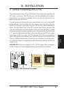
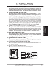
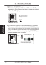
17. ATX Power Supply Connector (ATXPWR, 20-pin block)
This connector connects to an ATX power supply. The plug from the power
supply will only insert in one way because of the different hole sizes. Find the
proper orientation and push down firmly making sure that the pins are aligned.
IMPORTANT: Make sure that the ATX power supply can take at least 10mA
load on the 5-volt standby lead (5VSB). You may experience difficulty in pow-
ering on your system if your power supply cannot support the load.
ATX Power Connector
— 12.0V
— 5VSB
— PW-OK
— GND
— 5.0V
— GND
— 5.0V
— GND
— 3.3V
— 3.3V
GND —
3.3V —
5.0V —
5.0V —
5.0V —
GND —
GND —
GND —
PS-ON —
12.0V —
R