


32 ASUS SP97 / SP97-V User’s Manual
III. INSTALLATION
(Connectors)
III. INSTALLATION
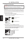
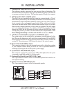
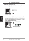
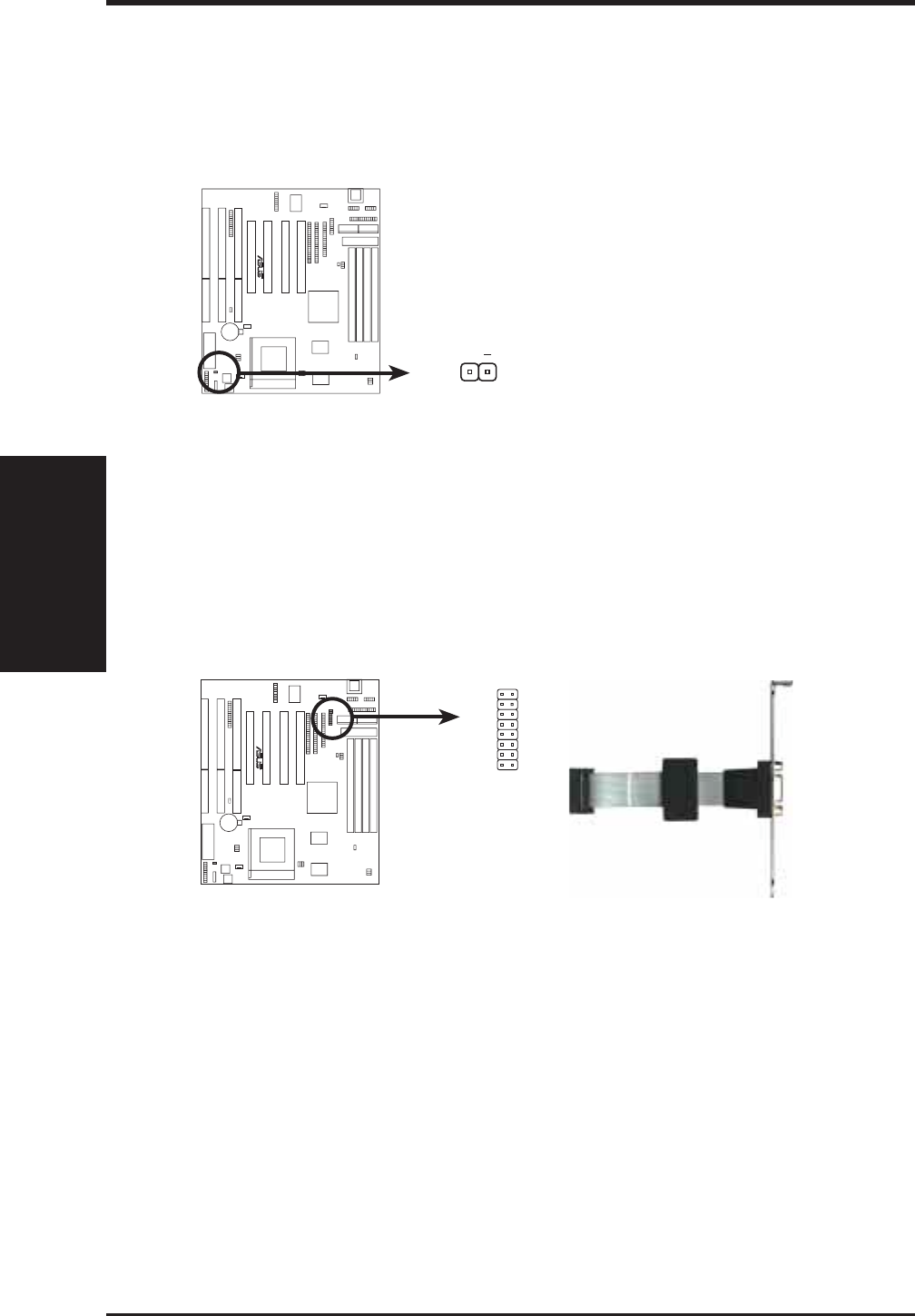
18. IDE Activity LED (IDELED, 2 pins)
This connector supplies power to the cabinet’s IDE activity LED. Read and
write activity by devices connected to the Primary or Secondary IDE connectors
will cause the LED to light up.
IDE Activity LED Lead
TIP: If the case-mounted LED
does not light, try reversing the
2-Pin plug.
IDE LED
R
+
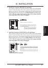
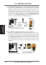
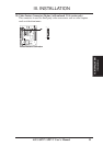
19. VGA Connector (VGACON, 16 pins) (with onboard VGA version only)
This connector, available only on motherboards with the SiS5598 chipset, sup-
ports the provided video or monitor cable with mounting bracket. Connect the
cable to this connector and mount the bracket to the case on a free expansion
slot. You can make available the monitor port by setting the VGA_SEL jumper
to Enable (see Jumpers for the VGA settings).
2
16
15
1
VGA (Monitor) Connector
R
Bracket to end approximately 6inch
Orient the red stripe on the
monitor cable with pin 1
TIP: You may also remove the bracket
connectors and mount them directly to
the case to save expansion slot space.