


CL1308 / CL1316 User Manual
6
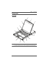
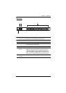
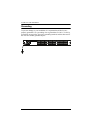
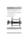
No. Component Description
1 Handle Pull to slide the KVM module out; push to slide the module in
(see item 2 in this table).
2 Slide Release In order to slide the console out, you must first release it by
sliding these tabs to the inside. See page 17 for details on
sliding the console in and out.
3 LCD Display After sliding the KVM module out, flip up the cover to access
the LCD monitor.
4 LCD Controls The LCD On/Off switch is located here, as well as buttons to
control the position and picture settings of the LCD display.
See page 21 for details.
5 Port LEDs An orange ON LINE LED lights to indicate that the computer
attached to its corresponding port is up and running. A green
Selected LED lights to indicate that the computer attached to
the corresponding port is selected for KVM control.
6 Keyboard Standard 105-key keyboard
7 Touchpad Standard mouse touchpad
8 Port Switches Press the port pushbuttons to bring the KVM focus to the
computer attached to the corresponding port.
9 Power LED Lights to indicate that the unit is receiving power.
10 Rack Mounting
Brackets
The rack mount brackets located at each corner of the unit
secure the chassis to a system rack.
11 Lock LEDs Num Lock, Caps Lock, Scroll Lock LEDs are located here.
12 Reset Switch Located to the right of the Lock LEDs. Press this recessed
switch in with a small object to perform a system reset.
13 Firmware
Upgrade
Section
Firmware Upgrade Port: The Firmware Upgrade Cable
that transfers the firmware upgrade data from the adminis-
trator's computer to the CL1308 / CL1316 plugs into this
RJ-11 connector.
Firmware Upgrade Switch: During normal operation this
switch should be in the NORMAL position. (See The Firm-
ware Upgrade Utility, page 45 for firmware upgrading
details.)