


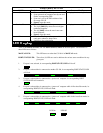
The Following DIP Switch settings are for the first-stage CS-104 ONLY
The DIP Switch settings for the second and third-stage CS104s are all switches off.
DIP Switch Number Function
1 2 3 4 Scan Time
ON ON X ON 3 Seconds
OFF ON X ON 10 Seconds
ON OFF X ON 20 Seconds
OFF OFF X ON 40 Seconds
FUNCTION
The
Foot Switch
is an extension of the front panel
Push Button
, both have the same function. Each time the
Foot Switch
is stepped on, a different computer is selected.
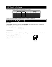
Foot Switch part # 2X-001 (Large)
2X-002 (Small)
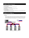
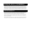
CONNECTION
The
Foot Switch
is connected to the CS-104 through a RJ-11 phone jack which is located on one side of the unit.
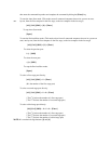
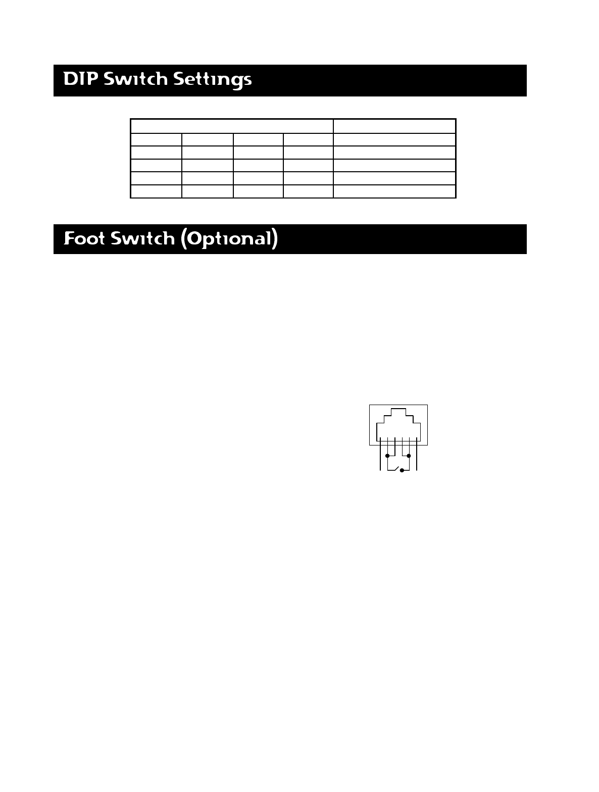
If you plan to install an ON/OFF switch to
work with the
Push Button
, check the
diagram to the right to ensure correct switch
connection.
1 2 3 4 5 6