26-Port Dual Web Rack Switch
6
2.5 AC Power
The Switch used the AC power supply 100-240V AC, 50-60 Hz. The power switch is located at the
rear of the unit adjacent to the AC power connector and the system fan. The switch’s power supply
will adjust to the local power source automatically and may be turned on without having any or all
LAN segment cables connected.
2.6 Identifying External Components
This chapter describes the front panel, rear panel, and LED indicators of the Switch.
Front Panel
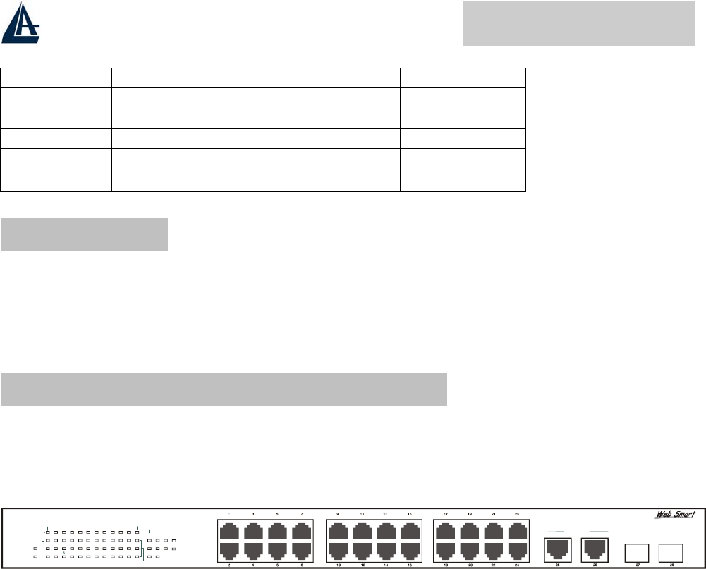
The figure below shows the front panels of the Switch.
28-Port 10/100/1000Mbps Web-SMART Gigabit Ethernet Switch
2
POWER
SYSTEM
4
810
12 14
16 18 20
22 24
13
5
7 9 11 13 15 17 19 21 23 25 26 27 28
Link/ACT
1000Mbps
100Mbps
10/100M
100Mbps
Link/ACT
Gigabit
1000BASE-T
Mini GBIC
26-Port Dual Web Rack Switch
LED Indicator::
Comprehensive LED indicators display the status of the switch and the network (see the LED
Indicators chapter below).
Fast Ethernet Ports (Port 1~24):
These ports support network speeds of either 10Mbps or 100Mbps, and can operate in half- and full-
duplex transfer modes. These ports also supports automatic MDI/MDIX crossover detection function
gives true “plug and play” capability, just need to plug-in the network cable to the hub directly and
don’t care if the end node is NIC (Network Interface Card) or switch and hub.
When the port was set to “Forced Mode”, the Auto MDI/MDIX will be disabled.
Gigabit Ethernet Ports (Port 25~26)::
The Switch is equipped with two Gigabit twisted pair ports, supported auto negotiable
10/100/1000Mbps and auto MDI/MDIX crossover detection function. These two ports can operate in
half-duplex mode for 10/100Mbps and full- duplex mode for 10/100/1000Mbps.
When the port was set to “Forced Mode”, the Auto MDI/MDIX will be disabled.
Mini-GBIC Ports (Port 27~28):
Technology Connector Distance
10 Base T RJ45 100m
100 Base TX RJ45 100m
1000 Base T RJ45 100m
1000 Base SX
LC (62.5µm multimode optical fibers)
275m
1000 Base SX
LC (50µm multimode optical fibers)
550m


