


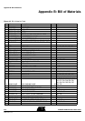

Hardware Description
2-8 AT89STK-06 Demo Board User Guide
4339B–CAN–11/04
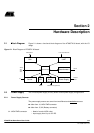
2.5.2 Solder straps Solder straps allow to modify the board configuration for specific usage such as
T89C51CC02 compatibility.
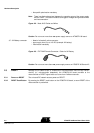
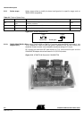
Figure 2-11. Solder Strap definition
2.5.2.1 T89C51CC02/T89C5115
Support (SP1)
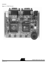
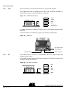
When using T89C51CC02 or T89C5115 products with the AT89STK-06 board ( see
¨PLCC adapter for T89C51CC02 user guide: CANADAPT28), the SP1 solder pad
should be closed to ensure correct hardware conditions setting on P1.0 port.
SP1 solder pad connects ISP push button to P1.0 microcontroller port and the
CANADAPT28 adapter should be inseted in U2 (PLCC44) socket.
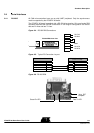
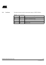
Figure 2-12. AT89STK-06 Board with CANADAPT28
Table 2-2. Table of Solder Strap
Reference PCB Name Comments (guidelines) Default
SP1
CC02 & C5115
mode
For T89C51CC02 usage, allows to redirect the ISP signal to P1.0, for
hardware conditions.
Open
SP2 X2_44 Connect PLCC44 Xtal2 to XTAL2 of the generic extension board (optionnal) Open
SP3 X2_52 Connect PLCC52 Xtal2 to XTAL2 of the generic extension board (optionnal) Open
Solder gout
Solder Pad
“Open”
“Close”