


AT89STK-06 Demo Board User Guide 2-3
Rev. 4339B–CAN–11/04
Section 2
Hardware Description
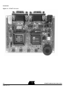
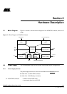
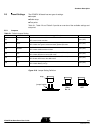
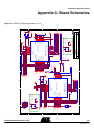
2.1 Block Diagram Figure 2-1 shows a functional block diagram of the AT89STK-06 board, with the I/O
usage.
Figure 2-1. Block Diagram of AT89STK-06 board
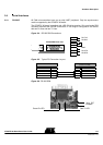
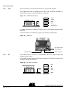
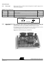
2.2 Power Supply The on-board power supply circuitry allows various power supply configurations.
2.2.1 Power Supply Sources
The power supply source can come from two different and exclusive
sources:
either from J4, JACK PWR connector
either from J5, 9V (Battery connector)
J4 - JACK PWR connector: – Need of a male JACK outlet
– Input supply from 6 up to 15V DC
CAN Network
CAN
Power SupplySensor LED
FLIP, Host, Batch ISP
Human
Reset,
ISP,
INT0,
Human
External
Power
Potentiometer
t°C
Generic
Connector
Board
Generic Board (optionnal)
UART
INT1
Applicable MCU