


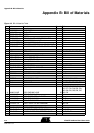

Appendix D: Default Configuration
AT89STK-06 Demo Board User Guide 4-19
4339B–CAN–11/04
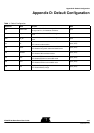
Appendix D: Default Configuration
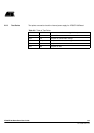
Table 1. Default Configuration
Reference Name Function State
SP1 CC02 mode
For T89C51CC02/T89C5115 usage, allow to redirect the
ISP signal to P1.0, for hardware conditions.
Open
SP2 X2_44
Connect PLCC44 Xtal2 to XTAL2 of the generic extension
board
Open
SP3 X2_52
Connect PLCC52 Xtal2 to XTAL2 of the generic extension
board
Open
JP1 EA
ON : allows external execution
OFF: Internal code execution
Open (OFF)
JP2 MUTE
ON : Enable C51 generic extension board buzzer
OFF: Disable C51 generic extension board buzzer
Open (OFF)
JP3 CANRes
ON : Enable CAN terminator resistor
OFF: Disable CAN terminator resistor
Open (OFF)
JP4 RTS
ON : Enable RTS line to control ISP mode
OFF: Disable RTS line to control ISP mode
Open (OFF)
JP5 DTR
ON : Enable DTR line to drive MCU reset
OFF: Disable DTR line to drive MCU reset
Open (OFF)
JP6 Batt
ON : Enable Battery charge
OFF: Disable Battery charge
Open (OFF)