


Using the STK502 Top Module
STK502 User Guide 2-3
2528A–AVR–11/02
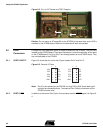
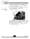
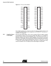
Figure 2-4. PORTG/RST
2.2.2.1 PG0 - PG5 These are general I/O ports connected to ZIF socket and the TQFP footprint.
2.2.2.2 RST
On the ATmega169 the RESET-signal and PG5 share the same pin. The “RST” is the
RESET
-signal that comes from the STK500 board. Please note that it is not directly con-
nected to the ZIF socket or the TQFP footprint on the STK502. This because the
RESET
-signal on the STK500 has an pull-up resistor to VCCT which will interfere with
PG5 when used as an ordinary I/O-pin.
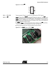
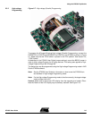
If RESET
/PG5-pin on ATmega169 shall be used as a Reset pin, the RST and PG5 on
the PORTG /RST
must be connected with a jumper. See Figure 2-5.
If the pin shall be used as an I/O-pin the jumper must be removed.
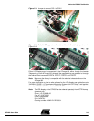
Figure 2-5. The RESET
Signal on PORTG/RST
PG0
PG2
PG4
NC
GND
PG1
PG3
PG5
RST
VTG
PORTG/RST
1 2