


11
ATTO Technology Inc. FibreBridge Installation and Operation Manual
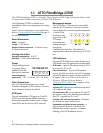
1.5 ATTO FibreBridge 2400C
The ATTO FibreBridge 2400C is a high performance bridge adding 4-Gigabit Fibre Channel connectivity to
legacy SCSI storage devices.
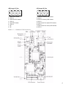
The FibreBridge 2400C is available in an industry-
standard 4U cPCI card for easy integration into storage
devices. Default values are appropriate for most
applications. Refer to
Configuring the FibreBridge
on page 15 for more information.
Board dimensions
Width:
6.1939 inches
Length:
6.299 inches
Height of tallest component:
.545 inches
Cooling and airflow
Operating temperature: 0-40 °C
Humidity: 10-90% non-condensing
Power
The FibreBridge
board may be
powered from the
cPCI backplane connector or a 6-pin connector.
Input voltage:
5.0V
Power draw:
30 Watts
Battery-backed event log SRAM & Real-Time-
Clock:
A rechargeable Lithium ion battery cell holds
the memory in a 512KB SRAM for up to 30 days.
WARNING
WARNING
Risk of explosion if the battery is removed
and/or replaced by an incorrect type.
Dispose of used batteries in accordance
with your local environmental regulations.
Explosionsgefahr, wenn die Batterie falsch
entfernt und/oder ersetzt wird. Entsorgen
Sie benutzte Batterien in Übereinstimmung
mit Ihren lokalen
Umweltschutzbestimmungen.
If the FibreBridge becomes disconnected from power,
recharging begins automatically when power is
restored to the system. The battery is fully charged
after 24 hours of continuous power application.
Fibre Channel port
The dual independent 4-Gb Fibre Channel ports can
connect the FibreBridge to either a Fabric or
Arbitrated Loop using a Small Formfactor Pluggable
(SFP) interface. The FibreBridge auto negotiates with
1-Gb, 2-Gb and 4-Gb/sec. devices
SCSI ports
The two SCSI ports connect storage devices into the
Fibre Channel Storage Area Network (SAN). Each
port is totally independent from the other.
The ports are Ultra320 SCSI busses with VHDCI
connectors, downward compatible with all forms of
single-ended SCSI and all previous SCSI protocols.
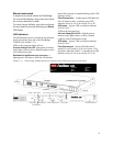
Management access
The 10/100 Base T Ethernet port is accessible from the
RJ-45 connector to support local and remote
diagnostics, monitoring and management.
A serial 10-pin
header provides
support for an RS-
232 remote
monitoring and
management port
through a Command
Line Interface. The baud rate is programmable and
preset at the factory to 115200 bps.
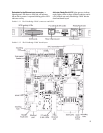
LED indicators
The on-board LED indicators show through the
faceplate and follow left to right.
SCSI ports:
a green LED indicates activity if it is lit,
no activity if it is off.
Fibre Channel port:
A lighted green LED indicates
link; off means no link. A separate green LED
indicates activity if it is lit, no activity if it is off.
Embedded in the Ethernet port connector:
a
lighted green LED shows a valid link; off indicates
that no link is present. A separate blinking yellow LED
indicates activity.
A bicolor Ready/Fault LED
lights green to indicate
ready, lights yellow to show a faulted condition, and is
off to indicate not ready.
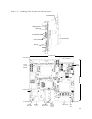
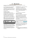
4 521 3 6
NU 5V GND 5V 5V GND
6-pin connection pinouts