


2727
2727
27
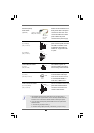
connect to the SATA
HDD power connector
connect to
the power
supply
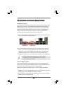
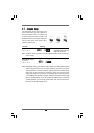
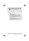
Serial ATA (SATA) Please connect the black end of
Power Cable SATA power cable to the power
(Optional) connector on each drive. Then
connect the white end of SATA
power cable to the power
connector of the power supply.
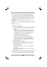
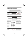
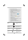
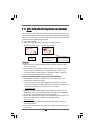
USB 2.0 Headers Besides six default USB 2.0
(9-pin USB8_9) ports on the I/O panel, there are
(see p.13 No. 23) two USB 2.0 headers on this
motherboard. Each USB 2.0
header can support two USB
2.0 ports.
(9-pin USB6_7)
(see p.13 No. 21)
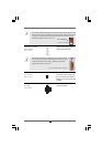
CD-L
GND
GND
CD-R
CD1
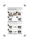
Internal Audio Connectors This connector allows you
(4-pin CD1) to receive stereo audio input
(CD1: see p.13 No. 27) from sound sources such as
a CD-ROM, DVD-ROM, TV
tuner card, or MPEG card.
USB_P WR
USB_P WR
P +7
P-7
P +6
P-6
GND
GND
DUMMY
1
1
USB_PWR
P-8
GND
DUMMY
USB_PWR
P+8
GND
P-9
P+9
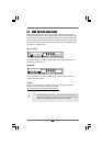
Infrared Module Header This header supports an
(5-pin IR1) optional wireless transmitting
(see p.13 No. 28) and receiving infrared module.
DUMMY
GND
+5V
IRTX
IRRX
1
J_S EN SE
OUT2_L
1
MIC _RET
P RESENCE#
GND
OUT2_R
MIC 2_R
MIC 2_L
OUT_R ET
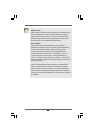
Front Panel Audio Header This is an interface for the front
(9-pin HD_AUDIO1) panel audio cable that allows
(see p.13, No. 26) convenient connection and
control of audio devices.
1. High Definition Audio supports Jack Sensing, but the panel wire on
the chassis must support HDA to function correctly. Please follow the
instruction in our manual and chassis manual to install your system.
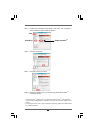
2. If you use AC’97 audio panel, please install it to the front panel audio
header as below:
A. Connect Mic_IN (MIC) to MIC2_L.
B. Connect Audio_R (RIN) to OUT2_R and Audio_L (LIN) to OUT2_L.