


6 DSR Switch Installer/User Guide
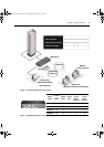
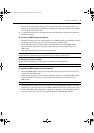
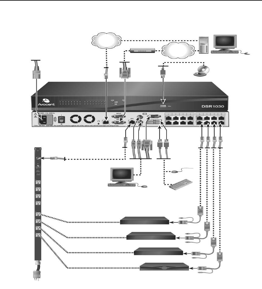
The following diagram illustrates one possible configuration for your DSR switch.
Figure 2.1: Basic DSR Switch Configuration
Digital User
Power
Telephone
Network
Ethernet
Cord
Modem
Analog User
SPC Port
Connection
Ports
1-16
CAT 5
Cable
SPC
Power Control
PS/2, USB*, Sun
and serial adaptors
are available.
* To open a virtual media session with a server,
the server must first be connected to the switch
using a virtual media capable DSRIQ module
(USB2 or USB2L).
DSRIQ Modules
Servers 1-16
DSR 1030 Switch
Device
DSR Switch_Atlantis.book Page 6 Wednesday, April 20, 2005 12:53 PM