


3 Equinox ESP Multi-Interface Serial Hub Product Installation Guide
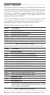
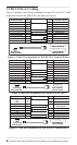
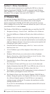
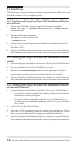
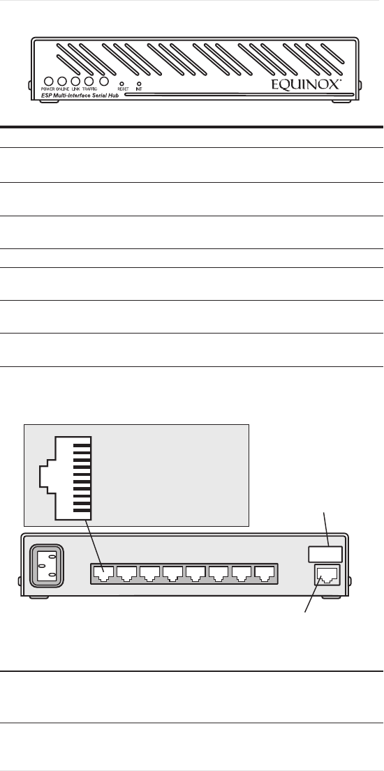
Figure 1 shows the front of the ESP-8 MI. Table 3 describes the LEDs and buttons.
Figure 1. ESP Front View
Item Description
POWER The POWER LED is lit when the ESP is connected to a
power source
ONLINE The ONLINE LED is lit (not blinking) when the ESP self-test
and initialization procedures have completed successfully
LINK The LINK LED is lit when the ESP recognizes that is has a
connection to the network
TRAFFIC The TRAFFIC LED blinks when there is network trafc
100MBps The 100MBps LED is lit when the ESP is connected to a
100 Mbps LAN
RESET Pushing the RESET button reboots the ESP; for more
information, see Section 1.4
INIT Pushing the INIT button restores the ESP to factory defaults;
for more information, see Section 1.4
Table 3. ESP LEDs and Buttons
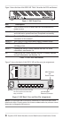
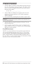
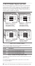
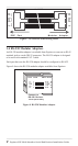
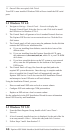
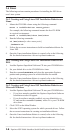
Figure 2 shows the back of the ESP-8 MI and the port pin assignments.
Figure 2. ESP Back View and Port Pin Assignments
NOTE: It is important that unused pins (labeled N/C) should not have wires
attached to them. Floating wires could cause unbalanced noise, shorten overall
distances and degrade performance.
1 2 3 4 5 6 7 8
0.5A
100-250 VAC, 50/60 Hz
Address
Serial #
LAN
10/100 BaseT
Ethernet Connector
MAC Address
and
Serial Number
Warning - The power outlet should be installed
near the equipment and should be
easily accessible.
Pin # RS-232 RS-422 RS-485
1 RTS N/C N/C
2 DTR Tx- N/C
3 N/C Tx+ N/C
4 DCD N/C N/C
5 Rx N/C N/C
6 Tx N/C N/C
7 GND GND GND
8 N/C Rx+ Rx/Tx+
9 N/C Rx- Rx/Tx-
10 CTS N/C N/C