


5 Equinox ESP Multi-Interface Serial Hub Product Installation Guide
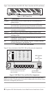
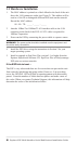
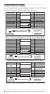
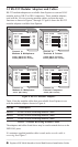
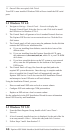
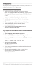
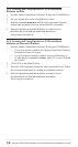
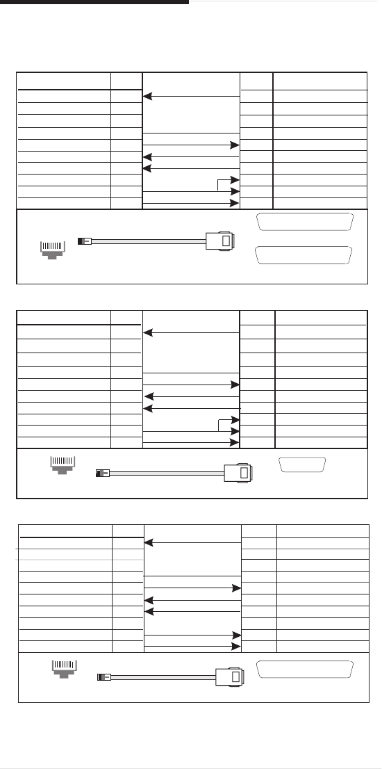
1.2 RS-232 Device Cabling
Figures 3 through 5 show the pin assignments required for an RS-232 cable
connection between the ESP RJ-45 ports and your devices.
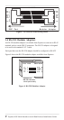
Figure 3. Cable Pin Assignments for ESP RJ-45 to Terminal/Printer
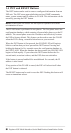
Figure 4. Cable Pin Assignments for ESP RJ-45 to PC DB-9
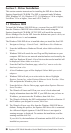
Figure 5. Cable Pin Assignments for ESP RJ-45 to Modem DB-25
9
7
6
5
4
3
2
1
N/C
Signal Ground
Transmit Data
Receive Data
Data Carrier Detect
N/C
DataTerminal Ready
Request to Send
4
Request to Send
6
Data Set Ready
7
Signal Ground
3
Receive Data
2
Transmit Data
20
DataTerminal Ready
8
Data Carrier Detect
5
Clear to Send
Pin #
To ESP RJ-45 Port
Pin #
ToTerminal / Printer
.
DB-25 (FEMALE)
1
..... .
..... .. ....
o
o o o o o o o
Cable EndView
DB-25 (MALE)
1
. .....
...... .....
.......
.
1
Cable EndView
RJ-45 (Plug)
..........
10
8
Clear to Send
N/C
9
7
6
5
4
3
2
1
7
6
5
2
3
4
1
8
N/C
Signal Ground
Transmit Data
Receive Data
Data Carrier Detect
N/C
DataTerminal Ready
Request to Send
Request to Send
Data Set Ready
Signal Ground
Receive Data
Transmit Data
DataTerminal Ready
Data Carrier Detect
Clear to Send
Pin #
Pin #
To ESP RJ-45 Port
To PC (DB-9)
.
1
Cable EndView
RJ-45 (Plug)
..........
Cable EndView
DB-9 (FEMALE)
1
o o o o o
o o o o
10
88
Clear to Send
N/C
9
7
6
5
4
3
2
1
4
N/C
Signal Ground
Transmit Data
Receive Data
Data Carrier Detect
N/C
DataTerminal Ready
Request to Send
5
Clear to Send
20
DataTerminal Ready
7
Signal Ground
2
Transmit Data
3
Receive Data
8
Data Carrier Detect
Request to Send
Pin #
Pin #
To ESP RJ-45 Port
To Modem
1
Cable EndView
RJ-45 (Plug)
..........
Cable EndView
DB-25 (MALE)
1
. .....
...... .....
.......
. .
10
8
ClearTo Send
N/C