


232XS53800 Manual
B&B Electronics -- PO Box 1040 -- Ottawa, IL 61350
PH (815) 433-5100 -- FAX (815) 433-5109
4
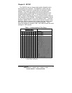
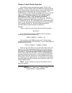
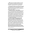
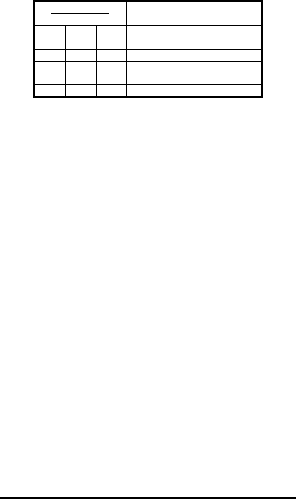
Table 2. Mode Setup
On = Jumper Installed Off = Jumper Removed X = DON'T CARE
* = FACTORY DEFAULT
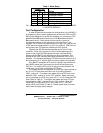
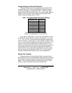
Port Configuration
In order to determine the proper port configuration of the 232XS5, it
is necessary to have a basic understanding of the terms DCE and DTE.
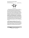
RS-232 was designed, using DB-25 connectors, for connecting a DTE
(Data Terminal Equipment) device to a DCE (Data Communication
Equipment) device. Each device will have inputs on pins that
correspond to outputs on the same pins of the other device. For
example, a DTE device will transmit data out on pin 2 (on a DB-25) and
a DCE device will receive data in on pin 2 (on a DB-25). IBM PCs and
serial printers are DTE devices, modems are DCE devices.
Originally the RS-232 standard specified only a 25 pin D-sub
connector. Since then, the use of a 9 pin D-Sub supporting only a
portion of the original RS-232 signals has been used extensively,
starting with the IBM PC and migrating into other peripherals. The
pinouts for this 9 pin connector have since become the EIA/TIA 574
standard. This standard specifies a DTE device that transmits on pin 3
and receives on pin 2, with the DCE having the opposite configuration.
If an IBM PC compatible (DTE device) is going to be connected to
the 232XS5 master port, the master port should be configured as a
DCE port. If a modem (DCE device) is going to be connected to the
master port, it should be configured as a DTE port.
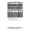
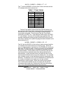
The master port can be configured as a DCE port (data received on
pin 3) or a DTE port (data received on pin 2) by setting dipswitch
“SW1”, position 8. To configure the master port as a DCE port, move
dipswitch “SW1”, position 8, to the "OFF" position. When the master
port is configured as a DCE port, ports A, B, C, D & E will become DTE
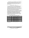
ports (Refer to Table 3). To configure the master port as a DTE port
move dipswitch “SW1”, position 8, to the "ON" position. When the
master port is configured as a DTE port, ports A, B, C, D & E will
become DCE ports (Refer to Table 4). Always power down the smart
switch when changing switch settings.
Jumper JP6
A B C
Setting
ON X X Enhanced Disabled *
OFF X X Enhanced Enabled
X ON X Smart Switch *
X OFF ON Expansion
X X ON Combiner Disabled *
X ON OFF Combiner Enabled