


232XS53800 Manual
B&B Electronics -- PO Box 1040 -- Ottawa, IL 61350
PH (815) 433-5100 -- FAX (815) 433-5109
6
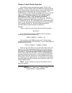
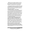
Serial Data Configuration
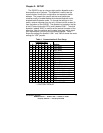
In order for the host device that is connected to the master port
to select any of the five ports, the Smart Switch must be set to
match the host's communication format. Dipswitch “SW1” is used to
select the communication format of the Smart Switch. Switch
positions 1 through 3 select the baud rate. Switch position 4 selects
7 or 8 data bits. Switch position 5 determines if parity is enabled or
disabled.
NOTE: A data format of 7 data bits, no parity and one stop is
not allowed.
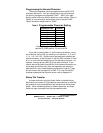
Switch position 8 selects the port configuration, see section titled
"Port Configuration". Refer to Table 1.
Always power down the
smart switch when changing switch settings.
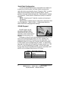
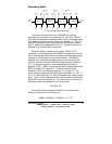
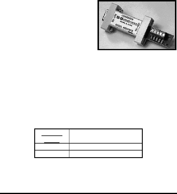
RS-485 Support
RS-485 support may be
provided by adding a Model
485SD9TB RS-232 to RS-485
converter or other recommended
device to the slave ports of the
232XS5.
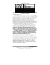
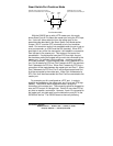
Port power of about 30 mA may be applied through the DTR line
(Pin 4) of the slave ports with jumper JP1-JP5. Normally, the
jumpers are set to allow DTR to pass from the master port. To
enable port power on a slave port, move the jumper from the“OFF”
to “ON” position on the corresponding JP jumper. To allow DTR to
pass from the master port to the slave port, move jumper from “ON”
to “OFF” on the corresponding JP jumper. DTR can only pass
through when the port is selected and the jumper is set to the “OFF”
position on the corresponding slave port JP jumper.
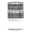
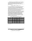
Table 5. Port Power Jumpers
* = FACTORY DEFAULT
Jumper
JP1-5
Setting
“OFF” DTR passed *
“ON” Port Power