


M3LDY
EM-2664 Rev.2P. 3 / 6
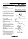
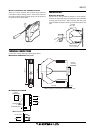
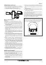
EXTERNAL & INTERNAL VIEWS
87654321
ON
OFF
ON
OFF
4321
Configuration DIP SW
10 11 12
789
456
123
Configurator Jack
DOWN Button
UP Button
MODE Button
LED3 (LD3)
LED2 (LD2)
LED1 (LD1)
■FRONT VIEW ■SIDE VIEW
SW2
SW1
ONOFF
SW3
CONFIGURATION MODE & DIP SW SETTINGS
When you program the transmitter module, two configura-
tion modes are available: Field Configuration using DIP SW
/ control buttons, and PC Software. (The Option B type is for
the field configuration only.)
The internal DIP switches are used to configure input and
output type. Once the module is configured, precise ranges
are set up with the front control buttons using a simulator
connected to the input terminals and a multimeter connected
to the output terminals as a reference.
The calibrated input and output ranges are stored in the
internal memory. The module reads the DIP-switch-cali-
brated configuration only once after the power supply is
turned on. Set the switches with the power supply removed.
Selectable I/O type and ranges are listed in Table 5 and 6.
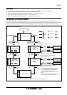
■ DIP SW CONFIGURATION MODE
Turn the SW2-8 OFF to enable the DIP SW (Field Configura-
tion) mode as shown in Table 1.
See Table 2 to configure the input and Table 3 for the output.
■ PC CONFIGURATION MODE
Turn the SW2-8 ON to enable the PC Configuration mode as
shown in Table 1. All programmable features can be set up
on a PC regardless of other DIP SW setting except that the
output type must be selected with the DIP SW1-1 through
SW1-4 (See Table 4).
For detailed information on the PC configuration, refer to the
M3CON instruction manual.
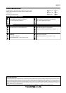
OUTPUT SW2-4 SW2-3 SW1-4 SW1-3 SW1-2 SW1-1
0 – 20mA OFF OFF OFF ON OFF OFF
-2.5 – +2.5V OFF ON ON OFF OFF ON
-10 – +10V ON OFF ON OFF ON OFF
OUTPUT SW1-4 SW1-3 SW1-2 SW1-1
0 – 20mA OFF ON OFF OFF
-2.5 – +2.5V ON OFF OFF ON
-10 – +10V ON OFF ON OFF
MODE SW2-8
DIP SW OFF
PC ON
Configuration mode can be
confirmed with the front LED.
■CONFIGURATION MODE (SW2) Table 1
■INPUT TYPE (SW2 & 3) Table 2
■OUTPUT TYPE (SW2 & 1) Table 3
■OUTPUT TYPE / PC CONFIG (SW1) Table 4
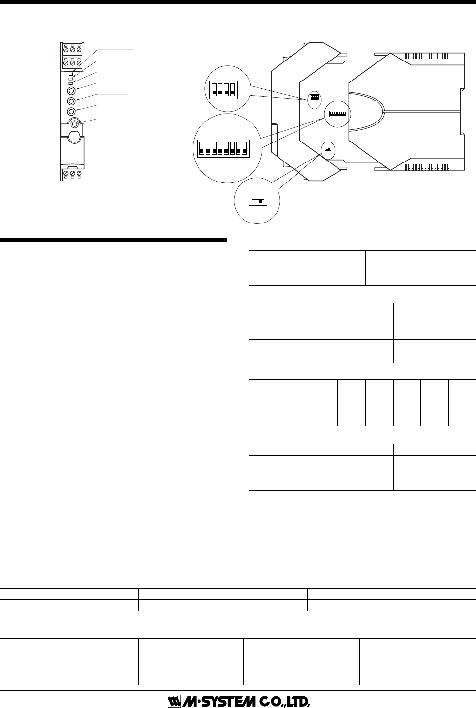
■ OUTPUT TYPE & RANGE Table 6
OUTPUT TYPE MINIMUM SPAN MAXIMUM RANGE CONFORMANCE RANGE
DC Current 1mA 0 to 20mA 0 to 24mA
DC Voltage, Narrow Spans 250mV -2.5 to +2.5V -3 to +3V
DC Voltage, Wide Spans 1V -10 to +10V -11.5 to +11.5V
■ INPUT TYPE & RANGE Table 5
INPUT TYPE MINIMUM SPAN MAXIMUM RANGE
DC Current 2mA 0 to 20mA
INPUT TYPE SW2-7 SW3
DC current
ON OFF
(isolator use)
2-wire loop
OFF ON
(
DC supply use
)