


M3LDY
EM-2664 Rev.2P. 5 / 6
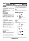
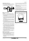
■ PREPARATION (e.g. M3LDY-R/A)
1) Mount the DIP-SW-configured M3LDY on to a DIN rail.
2) Connect the M3LDY to a simulator and a multimeter and
to a DC power source as shown to the right.
3) Turn the power supply on and wait for 10 minutes.
■ INPUT & OUTPUT RANGING
[Example]
Setting input to 4 – 20mA DC and output to 1 – 5V DC
1) Run Mode: Confirm that the LD1 green light is blinking.
2) Input Configuration Mode: Press MODE button for longer
than 5 seconds until the LD1 red light is ON and the LD2
red light is blinking.
3) 0% Input Ranging: Apply the desired minimum input
level (e.g. 4mA) from the simulator and push DOWN
button until the LD1 flashes for approx. 2 sec. and then
turns OFF. When you release the button, the LD1 is
returned to ON.
The flashing LD1 means that the value is stored in the
memory. If the LED does not change, the entered level
may be inappropriate: too small a span, or out of usable
range (same for all steps).
4) 100% Input Ranging: Apply the desired maximum input
level (e.g. 20mA) from the simulator and push UP button
until the LD1 flashes for approx. 2 sec. and then turns
OFF. When you release the button, the LD1 is returned to
ON.
5) Output Configuration Mode: Push MODE button and
confirm that the LD3 red light instead of LD2 is blinking.
6) 0% Output Ranging: Increase or decrease the simulated
input until the meter shows the desired minimum output
level (e.g. 1V). Push DOWN button until the LD1 flashes
for approx. 2 sec. and then turns OFF. When you release
the button, the LD1 is returned to ON.
7) 100% Output Ranging: Increase or decrease the simulated
input until the meter shows the desired maximum output
level (e.g. 5V). Push UP button until the LD1 flashes for
approx. 2 sec. and then turns OFF. When you release the
button, the LD1 is returned to ON.
8) Run Mode: Programming complete, push MODE button
and confirm that only the LD1 green light is blinking.
■ ZERO & SPAN ADJUSTMENTS
After the transmitter is installed and operational, fine zero
and span tuning can be performed as explained below. Both
zero and span are adjustable within ±15%.
1) Run Mode: Confirm that the LD1 green light is blinking.
2) Fine Zero Calibration Mode: Press MODE button for 1 or
2 seconds until the LD1 red light is ON and the LD2 green
light is blinking.
3) Use UP (increase) and DOWN (decrease) buttons to adjust
the output to 0%.
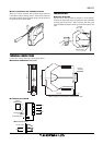
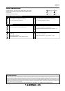
INPUT
OUTPUT
I/O Range Label (included in the product package)
■ I/O RANGE LABEL
Blank I/O range labels are included in the product pack-
age. Write in the configured ranges and put the label on
the side above the specification label as shown below.
4) Fine Span Calibration Mode: Push MODE button and
confirm that the LD3 green light instead of LD2 is blink-
ing.
5) Use UP (increase) and DOWN (decrease) buttons to adjust
the output to 100%.
6) Run Mode: Push MODE button and confirm that only the
LD1 green light is blinking.
Note 1: Calibration steps can be skipped when not needed by
repeating pushing MODE buttons.
Note 2: There is no stated order of setting 0% and 100% levels
or no limitation of entering values for multiple times within
one step of Calibration Mode. Signal level is stored each time
the respective UP or DOWN button is pressed.
2
3
7
8
11
12
M3LDY
Multimeter
Simulator
+
–
DC Power Source
+–
+
–