


M3LDY
EM-2664 Rev.2P. 4 / 6
CHECKING
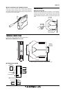
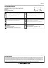
1) Terminal wiring: Check that all cables are correctly connected according to the connection diagram.
2) DIP SW setting: Check that the switches are set to appropriate positions.
3) Power input voltage: Check voltage across the terminal 11 – 12 with a multimeter.
4) Input: Check that the input signal is within 0 – 100% of full-scale.
5) Output: Check that the load resistance meets the described specifications.
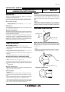
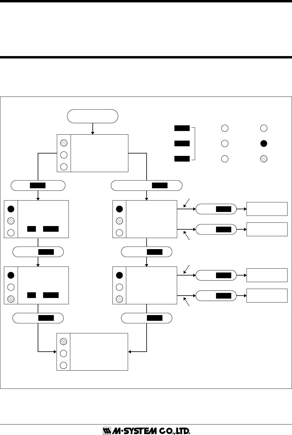
I/O RANGING & FINE ADJUSTMENTS
After the DIP SW setting is complete, set up the precise input and output range using the front control buttons.
The front LEDs’ colors and flashing patterns help you to easily identify the transmitter’s status and confirm the setup actions
in each step of Calibration Modes. Please read the following explanations referring to “Calibration Flow Chart” below.
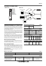
POWER ON
Amber LED
Green LED
Control
Buttons
Red LED
OFF
ON
Blink
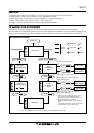
RUN MODE
LD1
LD2
LD3
A
G
RUN MODE
LD1
LD2
LD3
G
R
LD1
LD2
LD3
LD1
LD2
LD3
0% INPUT
CONFIGURED
100% INPUT
CONFIGURED
INPUT
CALIBRATION
MODE
LD1
OUTPUT
CALIBRATION
MODE
LD2
LD3
LD1
LD2
LD3
0% OUTPUT
CONFIGURED
100% OUTPUT
CONFIGURED
G
G R
R
R
R
G
R
R
G
Fine Adjustments ? I/O Ranging ?
PUSH
MODE
1 – 2 s PRESS & HOLD
MODE
> 5s
PUSH
MODE
PUSH
MODE
PUSH
MODE
PUSH
MODE
PUSH
DOWN
PUSH
UP
DOWN
UP
MODE
PUSH
DOWN
PUSH
UP
When you set 0% or 100% input/output ranges,
keep pressing UP or DOWN button until the
LD1 flashes for approx. 2 seconds and turns off,
which indicates the setup is complete.
When you release the button, the LD1 is returned
to ON.
If the LED does not change, the entered level may
be inappropriate, i.e. out of usable range.
FINE ZERO
CALIBRATION MODE
UP
or
DOWN
FINE SPAN
CALIBRATION MODE
UP
or
DOWN
Apply simulated 0% input signal.
Apply simulated 100% input signal.
Adjust simulated input until the output meter
shows desired 0% output.
Adjust simulated input until the output meter
shows desired 100% output.
*1. Fine zero and calibrations are performed for 0% and 100% output regardless of the input value.
*
1
*
1
■ CALIBRATION FLOW CHART