


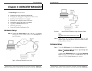

Making Hardware Connections
Manual Documentation Number: ESP901-902_4105m Chapter 2 13
B&B Electronics Mfg Co Inc – 707 Dayton Rd - PO Box 1040 - Ottawa IL 61350 - Ph 815-433-5100 - Fax 815-433-5104 – www.bb-elec.com
B&B Electronics Ltd – Westlink Commercial Pk – Oranmore, Galway, Ireland – Ph +353 91-792444 – Fax +353 91-792445 – www.bb-europe.com
Default Mode
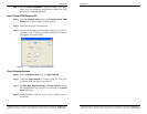
When
Default Mode is selected and the server properties are Updated
(
Saved) all the configuration settings return to their default values.
N
N
o
o
t
t
e
e
:
:
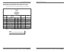
Refer to Chapter 5 for details on Serial Server Configuration settings.
See Chapter 12 for Serial Server default parameters.
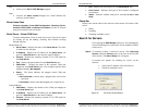
Console Mode
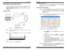
In Console Mode the Configuration Menu can be accessed from a PC
by connecting its RS-232 serial port to the ESP901 serial port or
ESP902 Serial Port 1. Since the computer is a DTE device, and the
serial ports are configured as DTEs (with DB-9M connectors), a null
modem crossover cable must be used.
In
Console Mode the default serial port settings are: 9600 baud, 8 data
bits, No parity, and 1 stop bit. From Windows, HyperTerminal with
VT100 terminal emulation can be used for Console Mode
configuration.
N
N
o
o
t
t
e
e
:
:
Refer to Chapter 9 for details on Console Mode
Upgrade Mode
In Upgrade Mode firmware can be uploaded from a PC via its serial
port to the ESP901 serial port or ESP902 Serial Port 1. Upgrading also
can be accomplished via the network connection, using the ESP
Manager software and a virtual COM port.
N
N
o
o
t
t
e
e
:
:
Refer to Chapter 8 for details on Upgrade Mode
RS-232 Mode
In RS-232 Mode the currently selected serial port is configured as an
RS-232 interface supporting eight RS-232 signal lines plus Signal
Ground and is configured as a DTE, like a computer. Signals are single
ended and referenced to Ground. To use handshaking, Flow Control
must be set to RTS/CTS during Configuration.
N
N
o
o
t
t
e
e
:
:
Refer to Appendix A for RS-232 connection pin-outs.
Making Hardware Connections
14 Chapter 2 Manual Documentation Number: ESP901-902_4105m
B&B Electronics Mfg Co Inc – 707 Dayton Rd - PO Box 1040 - Ottawa IL 61350 - Ph 815-433-5100 - Fax 815-433-5104 – www.bb-elec.com
B&B Electronics Ltd – Westlink Commercial Pk – Oranmore, Galway, Ireland – Ph +353 91-792444 – Fax +353 91-792445 – www.bb-europe.com
RS-422 Mode
In RS-422 Mode the currently selected serial port is configured as an
RS-422 interface supporting four RS-422 signal channels with full
duplex operation for
Receive, Transmit, RTS (Request To Send) and
CTS (Clear To Send). The data lines are differential pairs (A & B) in
which the B line is positive relative to the A line in the idle (mark)
state. Ground provides a common mode reference. To use handshaking,
Flow Control must be set to RTS/CTS during configuration.
N
N
o
o
t
t
e
e
:
:
Refer to Appendix B RS-422 connection pin-outs.
RS-485 Mode
In RS-485 Mode the currently selected port is configured as an RS-485
interface supporting transmit (TX) and receive (RX) signal channels
using 2-wire, half-duplex operation. The data lines are differential with
the Data B line positive relative to Data A in the idle (mark) state.
Ground provides a common mode reference.
N
N
o
o
t
t
e
e
:
:
Refer to Appendix C for RS-485 connection pin-outs.
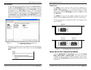
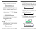
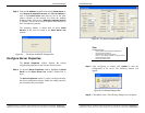
RS-485 Receiver Biasing
RS-485 Receiver Biasing
can be implemented from the Serial Server
if the network does not supply it. Remove the two side-cover screws of
the
Serial Server, slide the cover off and re-position the bias jumpers
(shown open in the figure below) to enable biasing (shorting).
Figure 10. Internal Setting to Select RS-485 Bias
N
N
o
o
t
t
e
e
:
:
(For more information on RS-485 Receiver Biasing, see B&B
Electronics RS-422/485 Application Note available at www.bb-
elec.com)