


Manual Documentation Number: ESP901-902_4105m Table of Contents i
B&B Electronics Mfg Co Inc – 707 Dayton Rd - PO Box 1040 - Ottawa IL 61350 - Ph 815-433-5100 - Fax 815-433-5104 – www.bb-elec.com
B&B Electronics Ltd – Westlink Commercial Pk – Oranmore, Galway, Ireland – Ph +353 91-792444 – Fax +353 91-792445 – www.bb-europe.com
T
T
a
a
b
b
l
l
e
e
o
o
f
f
C
C
o
o
n
n
t
t
e
e
n
n
t
t
s
s
TABLE OF CONTENTS ...................................................................................I
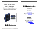
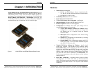
CHAPTER 1: INTRODUCTION..................................................................... 1
FEATURES......................................................................................................... 2
COMMUNICATION MODES ................................................................................ 3
Direct IP Mode ............................................................................................ 3
Virtual COM Mode ...................................................................................... 3
Paired Mode ................................................................................................ 4
Heart Beat.................................................................................................... 4
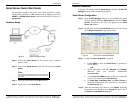
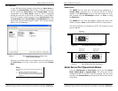
SERIAL SERVER QUICK START GUIDE .............................................................. 5
Hardware Setup ........................................................................................... 5
Software Installation.................................................................................... 6
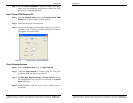
Serial Server Configuration......................................................................... 6
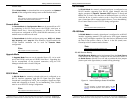
Install Virtual COM Ports on PC................................................................. 7
Check Communications ............................................................................... 7
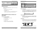
CHAPTER 2: MAKING THE HARDWARE CONNECTIONS .................. 9
PACKAGE CHECKLIST ....................................................................................... 9
ESP901/ESP902 CONNECTIONS, INDICATORS AND RESET SWITCH ................. 9
Indicator Lights.......................................................................................... 10
Ethernet Connector.................................................................................... 10
Power Connector ....................................................................................... 10
Reset Button ............................................................................................... 10
DIP Switches.............................................................................................. 11
Serial Ports ................................................................................................ 12
SERIAL SERVER/PORT OPERATIONAL MODES ................................................ 12
Default Mode ............................................................................................. 13
Console Mode ............................................................................................ 13
Upgrade Mode........................................................................................... 13
RS-232 Mode.............................................................................................. 13
RS-422 Mode.............................................................................................. 14
RS-485 Mode.............................................................................................. 14
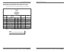
SERIAL SERVER SERIAL PORT CONNECTOR PIN-OUTS.................................... 15
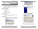
CHAPTER 3: INSTALLING THE VLINX ESP SOFTWARE .................. 17
SOFTWARE INSTALLATION.............................................................................. 17
Automatic Installation................................................................................ 17
Manual Installation.................................................................................... 17
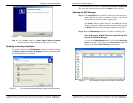
Updating an Existing Installation.............................................................. 19
Opening the ESP Manager ........................................................................ 20
ii Table of Contents Manual Documentation Number: ESP901-902_4105m
B&B Electronics Mfg Co Inc – 707 Dayton Rd - PO Box 1040 - Ottawa IL 61350 - Ph 815-433-5100 - Fax 815-433-5104 – www.bb-elec.com
B&B Electronics Ltd – Westlink Commercial Pk – Oranmore, Galway, Ireland – Ph +353 91-792444 – Fax +353 91-792445 – www.bb-europe.com
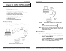
CHAPTER 4: USING ESP MANAGER........................................................ 21
HARDWARE SETUP ......................................................................................... 21
SOFTWARE SETUP........................................................................................... 22
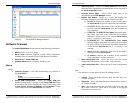
SOFTWARE OVERVIEW ................................................................................... 23
Menus......................................................................................................... 23
Server Icons Pane...................................................................................... 25
Serial Server / Virtual COM Lists.............................................................. 25
Status Bar................................................................................................... 26
SEARCH FOR SERVERS .................................................................................... 26
CONFIGURE SERVER PROPERTIES ................................................................... 27
CHAPTER 5: CONFIGURING THE SERIAL SERVER PROPERTIES. 31
DESCRIPTION OF THE SERVER PROPERTIES..................................................... 32
Server Name............................................................................................... 32
Serial Number............................................................................................ 32
Password.................................................................................................... 32
DHCP ........................................................................................................ 32
IP Address.................................................................................................. 33
Netmask...................................................................................................... 34
Gateway ..................................................................................................... 34
MAC Address............................................................................................. 34
Version & Date .......................................................................................... 34
Link Status.................................................................................................. 34
Server Serial Port ...................................................................................... 34
Baud Rate................................................................................................... 34
Data/Parity/Stop........................................................................................ 34
Flow Control.............................................................................................. 35
TCP/UDP Protocol.................................................................................... 35
Serial Timeout............................................................................................ 35
TCP Alive Timeout..................................................................................... 36
Connection Mode....................................................................................... 36
Delimiter HEX 1 and Delimiter HEX 2...................................................... 36
Force Transmit........................................................................................... 36
Port Status.................................................................................................. 37
TCP/UDP Port........................................................................................... 37
Serial Port Mode........................................................................................ 37
Connection At ............................................................................................ 38
Max Connection......................................................................................... 38
Remote IP Address..................................................................................... 38
Update/Save............................................................................................... 38
CHAPTER 6: INSTALLING VIRTUAL COM PORTS ............................. 43
VIRTUAL COM PORT INSTALLATION ............................................................. 43
MATCHING THE SERIAL SERVER AND VIRTUAL COM PORT SETTINGS .......... 46