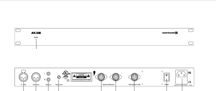
MCS 20 – Power Supply Unit
30
2.2 Controls and indicators
ᕡ Power on LED
ᕢ Audio input, 3-pin XLR, balanced, ungrounded, adjustable via “Input Level” potentiometer ᕥ
ᕣ Audio output, 3-pin XLR, balanced, ungrounded
ᕤ Line output, e.g. for recorders
ᕥ Input level control
ᕦ Connection for more power supply units / system extension
ᕧ Connection for microphone units
ᕨ On/Off switch
ᕩ Power connection with fuse holder
MCS 20 front view
MCS 20 rear view
ᕡ
ᕢ
ᕣ ᕤ ᕥ ᕦ ᕦ ᕧ ᕨ ᕩ
2.3 Operation
Power connection
• Check whether the connection figures comply with the existing mains supply. Serious damage could occur due to
connecting the system to the wrong power supply.
• Make sure the power cable cannot be damaged or severed by sharp objects.
• Connect the MCS 20 power supply unit to the mains. Make sure the mains cable is firmly connected to the
MCS 20 power connection ᕩ. The fuse holder contains a 3.15 AT fuse.
Renk sockets
• The MCS 20 power supply unit provides Renk sockets to connect further MCS 20 power supply units ᕦ and
microphone units ᕧ. Further microphone units can be connected to the individual power supply units. Refer also
to chapter 4. “Examples of a system configuration”.
Note: Please make sure that the microphone units are connected to the appropriate connection ᕧ only.
• Also please ensure that pin no. 8 of the Renk sockets is always grounded while in use, so that pin no. 3 of the
Renk socket has +24 V with reference to ground and pin no. 7 of the Renk socket has -24 V with reference to
ground.
Audio connections
• Audio input ᕢ, 3-pin XLR socket, input, balanced, ungrounded; can be adjusted with the “Input Level” potentiometer.
The input signal is routed to the loudspeakers of the microphone unit and released via the audio output.
Connection:
1 = System ground (No connection to the protective earthing conductor to avoid hum!)
2 = +Signal
3 = -Signal


