


5.4.3 VOLTAGES AT VARIOUS PINS OF IC LM324 IS AS FOLLOWS ( IC-101 ) :-
IC PIN NO. VOLTAGES & CHECK CONDITIONS
PIN1 -- 0V ( WHEN V POT KEPT AT MIN. POSITION IN CV MODE )
PIN1 -- +5V ( WHEN V POT KEPT AT MAX. POSITION IN CV MODE )
PIN2 & 3-- +4.9V AT V POT MAX. POSITION.
PIN4 -- +12V ALL CONDITION
PIN7 -- 0V AT CC POT MIN. POSITION.
PIN7 -- 0.5V AT CC POT MAX. POSITION.
PIN8 -- +1V TO 3.5V IN CV MODE.
PIN8 -- +10V TO +11V IN CC MODE.
PIN9 -- 0V.
PIN10 -- -6mV.
PIN14 -- +10 TO 11V IN CV MODE.
5.4.4 A. CHECK VOLTAGES AT D3 CATHODE +2V (CV) +10V (CC)
B. CHECK VOLTAGES AT D4 CATHODE +10V (CV) + 2V (CC)
C. CHECK VOLTAGES AT Z101 CATHODE -4.7V
D. CHECK VOLTAGES AT Z102 CATHODE +10V
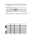
5.4.5 CHECK ALL REGULATORS OUTPUT WITH RESPECT TO OUTPUT
+VE COMMON.
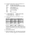
REF. PCB NO. PART NO. PIN NO. VOLTAGES
U1 IC7812 3 +12V
U2 IC79L05 3 -5.0V
U3 IC7805 3 +5.0V
CHECK WITH RESPECT TO OUTPUT -VE AS COMMON.
U4 IC7812 3 +12.0V
All the above readings are approximate values. The given voltages & waveforms
are refering to a normal working unit. If find any Voltage or Waveform absent at
given points, then trace back to the associated circuits. This complets basic trouble
shooting test points.
5.5 PARTS ORDERING & REPLACING :
5.5.1 OBTAINING REPLACEMENT PARTS : Most electrical parts can be obtained
through your local distributor or representative. However you should be able to
obtain many of the standard components from a local commercial source in
13