


Page 14
724-746-5500 | blackbox.com
Chapter 3: Installation
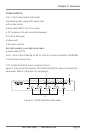
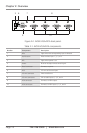
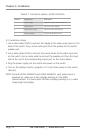
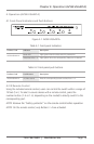
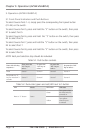
Table 3-1. Connection pattern, AVSW-VGA4X1A.
Number Component Description
1 Power supply Apply the proper power to the unit.
2 Video output Connects to the display.
3 Video source (input) Connects to the video source.
4 Serial connector Plug the serial cable in here.
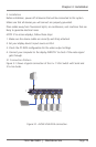
3.2 Installation Steps
1. Use a video cable (VGA) to connect the display to the video output port on the
back of the switch. Plug a set of audio jacks from the speaker to the switch’s
speaker port.
2. Use a video cable (VGA) to connect the source device to the video input port
on the switch. Use an audio cable to connect the speaker port from the input
side of the unit to the corresponding output port on the source device.
3. Plug the power supply into the switch and power on the switch.
4. Turn on the display (monitor, projector, or TV) and then power on the source
device(s).
NOTE: For both AVSW-VGA4X1A and AVSW-VGA8X1A, each video source is
powered on, make sure it has a display pointing to it for EDID
communication. If a source does not have a display pointing to it, a video
image might not display.