


Model AC504A-WP
6
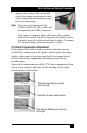
4. Plug in the supplied Power supply to the
Power Input jack on the rear of the sender
unit.
On the rear of the unit next to the RJ45
connector, there is a 2 pin screw terminal
for power connection.
You need to connect 9 vDC to these
terminals.
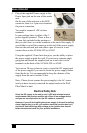
In your package there is either of the 2
power supplies pictured. There is also a
2.5 mm Jack included in the package so
that you don’t have to cut the connector at the end of the supply. If
you decide to cut off the connector on the end of the power supply,
then use the enclosed jack and solder a pair of wires to it and
connect those to the AC504A-WP or AC602.
Using the supplied 2.5mm Jack also gives you the ability to place
the power supply outside the wall. You can use a separate single
gang plate and install the supplied jack on it and wire it to the
terminals on the back of the AC504A-WP or AC602.
You can use 20 awg or heavier wire to extend the DC output cord
of the power supply if you need to locate the power supply farther
from the device. It is recommended to keep the distance of the
supply from the unit to within 30 feet.
Note: Please do not connect the power supply to the AC source
until you have securely connected the output cords to the Wall
Plate Mini-Cat unit.
Electrical Safety Note
Since the DC supply to the unit is only 9 vDC with minimal current
requirements, the product qualifies as a Class 2 low-voltage device,
and you are not required to run the DC cables in a conduit.
However if you will be installing the power supply in the wall or ceiling,
since it has to plug in to AC, you need an electrical junction box for it,
and the AC line that brings high-voltage to the junction-box should
follow the electrical code for your specific installation