


ServSwitch Agility and Agility Dual
724-746-5500 | blackbox.com
Page 16
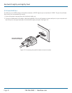
COMP
DVI-D
DVI-D link from
host computer
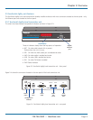
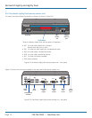
3.2 Connections
Installation involves linking the ServSwitch Agility local transmitter unit to various ports on the host computer, while the
ServSwitch Agility remote receiver unit is attached to your peripherals.
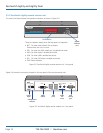
3.2.1 Local Video Link
The ServSwitch Agility and Agility Dual units support DVI digital video signals and so use DVI-D video connectors throughout.
• ServSwitchAgilitymodelscansupportasinglehighresolutionDVI-Dvideodisplayatpixelclocksupto165MHz(equatingto
an example display mode of 1920 x 1200 at 60Hz refresh).
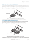
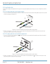
• ServSwitchAgilityDualmodelscansimultaneouslysupportuptotwoSingleLinkhighresolutionvideodisplaysatpixelclocks
up to 165MHz; or can alternatively support a single Dual Link very high Resolution video display at pixel clocks up to 330MHz
(equating to an example display mode of 2560 x 1600 at 60 Hz refresh).
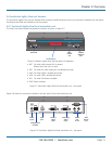
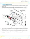
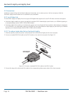
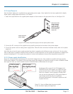
3.2.1.1 To make a single video link on ServSwitch Agility
1 Wherever possible, ensure that power is disconnected from the ServSwitch Agility and the host computer.
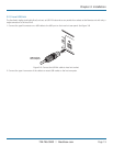
2 Connect a standard DVI-D link cable to the DVI-D socket on the Local unit rear panel. See Figure 3-3.
Figure 3-3. Connect a standard DVI-D link cable to the DVI-D socket.
3 Connect the plug at the other end of the cable to the corresponding video output socket of the host computer.