


Chapter 2: Overview
724-746-5500 | blackbox.com
Page 9
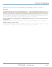
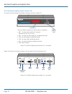
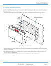
AUX
LINE IN
LINE OUT
COMPUTER
ON
21
INDOOR
USE ONLY
OPTIONS
1 2
5V
2.5A
DVI-D
Video
input
Audio
line
in/out
AUX
(serial)
port
USB
port
Configuration
switches
Power
input
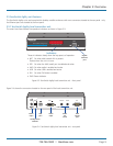
2.5 ServSwitch Agility unit features
The ServSwitch Agility units are housed within durable, metallic enclosures with most connectors situated at the rear panel - only
the Ethernet ports are situated at the front panel.
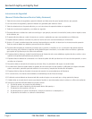
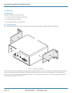
2.5.1 ServSwitch Agility local transmitter unit
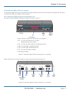
The smart front faces feature the operation indicators as shown in Figure 2-3:
NET SER
AUD
USB DVI PWR
LOCAL
ServSwitch Agility
™
BLACK
BOXKVMoIP
EXTENDER
Gigabit
Ethernet
port
Indicators
These six indicators clearly show the key aspects of operation:
• NET Onwhenvalidnetworklinkispresent.
Flashes when the unit is in error.
• SER OnwhentheAUX(serial)portisenabledandactive.
• AUDOnwhenaudioisenabledandactive.
• USB OnwhenUSBisenabledandactive.
• DVI OnwhenDVIvideoisenabled.
• PWR Powerindicator.
Figure 2-3. ServSwitch Agility local transmitter unit - front panel
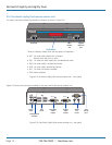
Figure 2-4 shows the connectors located on the rear panel of the local transmitter unit:
Figure 2-4. ServSwitch Agility local transmitter unit - rear panel