


Chapter 3: Installation
724-746-5500 | blackbox.com
Page 23
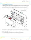
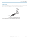
3.2.6.2 To link Agility Dual units using fiber optic links
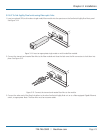
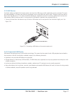
1 Insert an optional SFP (multi mode or single mode) fiber module into the aperture on the ServSwitch Agility Dual front panel.
See Figure 3-14.
S er vS wi tc h Ag il it y Du al
™
B L A C K
B O X K V M o I P
E X T E N D E R
REMOTE
S er vS wi tc h Ag il it y Du al
™
B L A C K
B O X K V M o I P
E X T E N D E R
REMOTE
Figure 3-14. Insert an appropriate single mode or muilti mode fiber module.
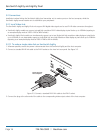
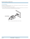
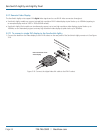
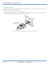
2 Connect the transmit and receive fiber links to the fiber module and close the latch over the link connectors to lock them into
place. See Figure 3-15.
Figure 3-15. Connect the transmit and receive fiber links to the module.
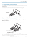
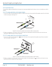
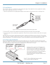
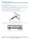
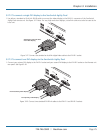
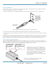
3 Connect the other end of the fiber links either to the other ServSwitch Agility Dual unit or to a fiber-equipped Gigabit Ethernet
switch, as appropriate. Note: The fiber links must be crossover cables.