


21
®
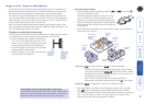
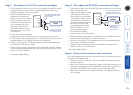
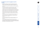
Stage C - Recongure the LOCAL connections and begin
1 On the computer from which you will run the upgrade, ensure that its BIOS
settings will allow it to boot from the oppy diskette drive, rather than
booting immediately from the hard drive.
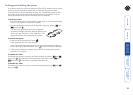
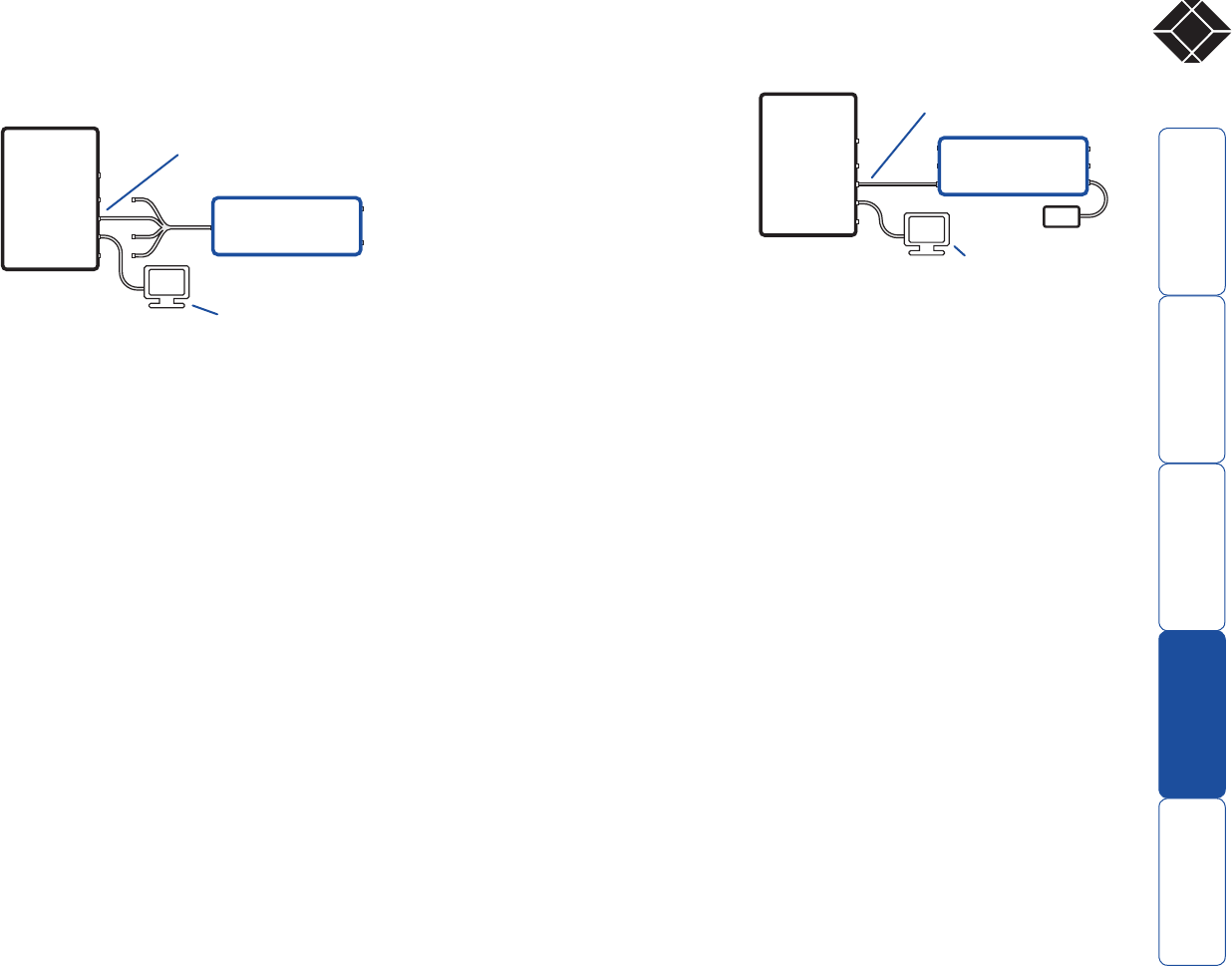
2 Switch off the computer and
disconnect the twisted pair
cable from the LOCAL module.
3 On the multi-cable, leave the
keyboard connector attached
to the keyboard port of the
computer. Disconnect the
multi-cable video and mouse
connectors from the ports on
the computer.
4 So that you can check upgrade
progress, connect a monitor directly to the video port of the computer.
5 On the LOCAL module, change switch 1 to the ON position. Ensure that the
upgrade diskette is in the oppy disk drive of the computer.
6 Switch on the computer. The upgrade process will start automatically and
conrmation will be given on screen.
7 Switch off the computer and disconnect the multi-cable. Leave the monitor
connected and the upgrade diskette in the oppy disk drive. Return LOCAL
switch 1 to the OFF position.
Now please follow Stage D.
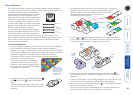
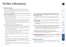
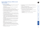
Stage D - Recongure the REMOTE connections and begin
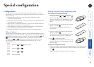
1 Disconnect all cables from the REMOTE module and take it to the computer.
2 Use a ‘KVM switch-type’
keyboard cable (6pin mini-DIN
male to 6pin mini-DIN male
plugs with all lines connected)
- not supplied. Attach one end
of the cable to the keyboard
port of the computer. Connect
the other end of the cable
to the keyboard port of the
REMOTE module. This is the
only connection required.
3 On the REMOTE module,
change switch 1 to the ON position.
4 Attach the power supply unit to the POWER input of the REMOTE module
and connect the mains lead to a nearby wall socket.
5 Switch on the computer. The upgrade process will start automatically and
conrmation will be given on screen.
6 Switch off the computer and disconnect the REMOTE module. Return
REMOTE switch 1 to the OFF position.
Now please follow Stage E.
Stage E - Return all connections to their usual states
Once the upgrade process has been completed, perform the following to return
the system to its previous state.
1 Ensure that switch 1 on both the LOCAL and REMOTE modules are set to
their OFF positions.
2 Refer to the ‘Installation and operation’ chapter for detailed instructions on
correctly connecting the LOCAL and REMOTE modules to the computer, its
peripherals, the REMOTE power supply and the twisted pair cable.
3 Remove the diskette from the system and reboot. The upgrade process is
now complete.
Leave only the keyboard connection
intact between the LOCAL module
and the computer
Connect a video monitor
to the computer so that
you can check progress
PC
Wizard Extender
LOCAL
AUDIO
VIDEO
KEYBO
ARD
MOUSE
RS232 SERIAL
Leave the video monitor
connected to the
computer so that you
can check progress
Use a KVM switch-type keyboard
connection cable between the
REMOTE module and the computer
PSU
PC
Wizard Extender
REMOTE
AUDIO
VIDEO
KEYBOARD
MOUSE
RS232 SERIAL