


8
®
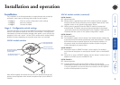
Stage C - Connections
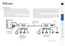
The naming of the LOCAL and REMOTE modules relate to their proximity to the
computer system. Hence, the LOCAL module connects directly to the system
(and the local peripherals), while the REMOTE is at the other end of the twisted
pair cable and attaches to the duplicate keyboard, mouse, etc.
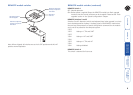
Connections at the LOCAL module
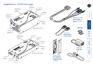
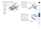
Multi-cable connection
Most of the connections between the computer system and the LOCAL module
are made via the supplied multi-cable. This has a single connection to the
module, is two metres in length and splits out to the keyboard, video and mouse
ports of the system.
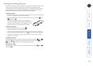
1 Attach the supplied
multi-cable to the
25-way socket
at the end of the
LOCAL module.
2 At the other end
of the multi-
cable, attach the
keyboard, mouse
and video, (plus
optionally on
ACU5116A variant,
the microphone and
speaker) connectors
to the appropriate
sockets at the rear
of the computer system. On most systems the appropriate ports should be
labelled and colour coded in a similar way to the cable connectors:
Monitor (video) Blue
Keyboard Purple
Mouse or Mid green
Speaker or
SPK
Light green
Microphone or
MIC
Pink (or maroon)
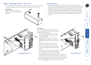
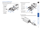
Serial cable connection
The Wizard extender modules offer the option to attach an RS232 serial device
(such as a touch screen input) via the remote link. The link supports software
or hardware handshaking up to a maximum baud rate of 56Kb/s. To make the
serial connection between the LOCAL module and your computer system, use
the supplied serial link cable.
Note: It is not possible to attach a duplicate serial device at the LOCAL module.
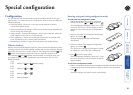
1 Attach male connector of
the serial link cable to the
9 pin port on the LOCAL
module, labelled .
2 Connect the other end of
the serial link cable to the
appropriate serial port of the
computer system.
LOCAL
CPU / KVM SWITCH
VIDEO OUT
Multi-cable main
connector
TO
REMO
TE
POWER
Male connector
of the serial cable
LOCAL
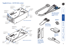
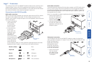
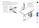
Twisted pair connection
The link between the LOCAL and REMOTE modules is made via twisted pair
cable, specied to Category 5 or higher. Ensure that the total twisted pair cable
length (including patch
boxes) does not exceed
984 feet (300 metres)
for ACU5114A variants
or 656 feet (200 metres)
for ACU5116A variants.
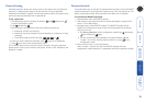
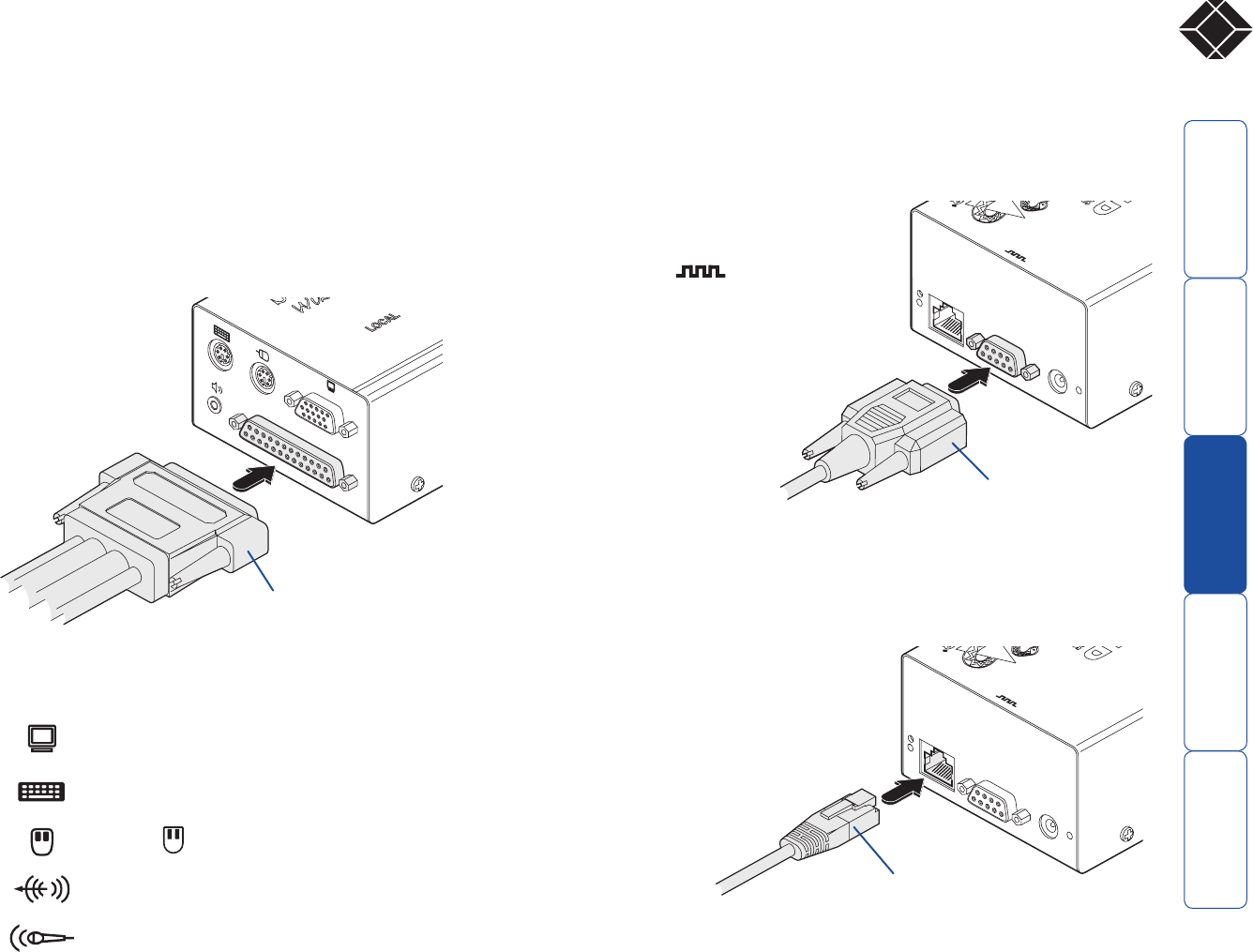
1 Insert the connector
from the twisted
pair cable link into
the socket marked
‘TO REMOTE’.
TO
REMO
TE
POWER
twisted pair
cable connector
LOCAL