Chapter 2: Installation
724-746-5500 | blackbox.com 2-9
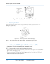
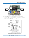
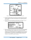
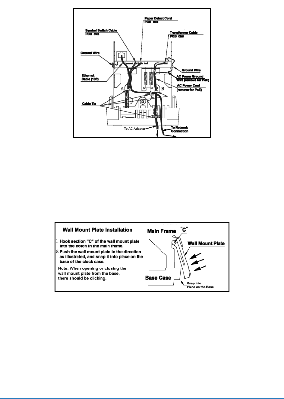
Figure 2-12. Rear View Showing AC Power Line For Removal.
10. Unscrew the Phillips head screw and remove the black ground wire for the AC
line (see Figure 2-12). Remove the AC power line from the back of the clock
with the transformer at the end. You may have to cut a couple of plastic wire
ties to do this.
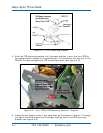
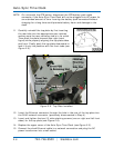
11. Reinstall the wall mounting plate (see figure below) on the back of the clock
using caution to verify that the Ethernet cable is properly routed.
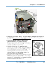
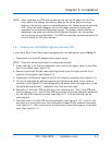
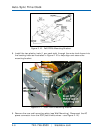
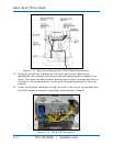
12. Plug in the FPR battery pack cable (the connector with the black and red wires)
into the small open connector (see Figure 2-13) located just under the battery
pack on the PCB. Next, plug in the PoE connector to the left of the FPR
connector for the PoE cable (yellow wires). It is keyed and can only fit into the
connector one way. The connection for the PoE cable has a 5-pin connector on
the main PCB and a 5-pin connector at the PoE PCB. Both connector ends are
keyed (can only fit in one way). You may have to temporarily remove the
connector on the PoE PCB to install the top plate.


