


Interface Pinouts
87
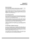
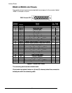
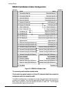
V.35 Null-Modem Cable Configuration
Protective GND
Transmitted Data (A)
Transmitted Data (B)
Received Data (A)
Received Data (B)
Transmitter Signal Element Timing (A)
Transmitter Signal Element Timing (B)
Receiver Signal Element Timing (A)
Receiver Signal Element Timing (B)
Transmitter Signal Element Timing (A)
Transmitter Signal Element Timing (B)
Data Terminal Ready
Signal Ground
Data Channel Received Line Signal Detector (CD)
Request to Send
Data Set Ready
Transmitter Signal Element Timing (A)
D
B
2
5
M
A
L
E
1
9
10
11
12
18
19
14
16
23
25
20
7
8
4
6
D
B
2
5
M
A
L
E
1
11
12
9
10
14
16
23
25
18
19
8
7
20
6
4
Transmitted Data (A)
Received Data (A)
Transmitted Data (B)
Received Data (B)
Receiver Signal Element Timing (A)
Receiver Signal Element Timing (B)
Transmitter Signal Element Timing (B)
Transmitter Signal Element Timing (A)
Transmitter Signal Element Timing (B)
Data Channel Received Line Signal Detector (CD)
Data Terminal Ready
Signal Ground
Data Set Ready
Request to Send
Protective GND
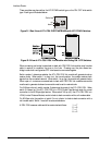
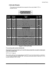
Figure D – 10 V-35 Null-Modem Cable
The connecting cable must be a shielded cable.
Circuits which are paired (contain an (A) and (B) reference) should be connected to
twisted pairs within the connecting cable.
This cable is needed when it is necessary to connect two units back-to-back and
a set of modems is not available. Note that this cable specifies DB25 connectors
on each end to allow direct connection to the link interface connector on each
unit.
The link speed must be defined for each of the two units.