


724-746-5500 | blackbox.com
724-746-5500 | blackbox.com
Page 101
Chapter 4: E2 Controller
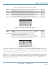
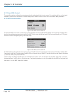
The number shown for Unit 2 is three, the result of adding 1 + 2. This confirms that Unit 2's supply temperature and return
humidity sensors are detected by the lead controller. If a one appeared instead for Unit 2, it would indicate the signal for the
return humidity sensor is not present. That sensor is either not enabled or it has failed.
4.7 BMS Communications
When BMS communication are used, the controller must be equipped with an optional expansion card designed for one of a
variety of serial communications protocols available (see Section 4.1.4). A communications port on the expansion card allows the
controller to be field connected to a central Building Management System (BMS) for monitoring and control of data points.
An RS-485 serial port is available for Modbus or BACnet MS/TP protocols and a 10BASE-T port is available for TCP/IP based
protocols such as BACnet over IP, BACnet over Ethernet, SNMP, or HTTP.
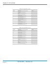
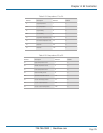
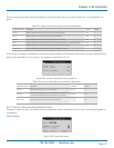
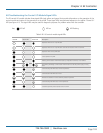
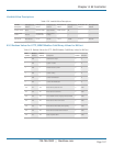
Table 4-25. BMS communications parameters.
Supported Protocols Media Connection
BACnet over IP 10BASE-T
RJ-45 direct
BACnet over Ethernet 10BASE-T
RJ-45 direct
HTTP 10BASE-T
RJ-45 direct
SNMP V1, V2c 10BASE-T
RJ-45 direct
Modbus over IP 10BASE-T
RJ-45 direct
BACnet MS/TP Twisted pair
Daisychain
Modbus RTU Twisted pair
Daisychain
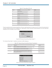
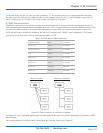
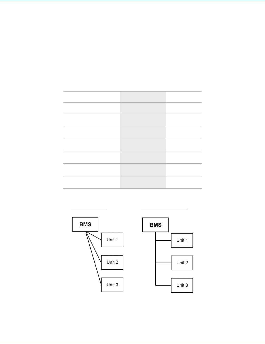
Direct Connection Daisychain Connection
Figure 4-91. Direct connection vs. daisychain connection.
If multiple A/C units are grouped together, each controller added to the group must be configured with a CPU address for BMS
communication.
For complete details on using BMS control, contact Black Box Technical Support (see Chapter 6).