


724-746-5500 | blackbox.com
724-746-5500 | blackbox.com
Page 97
Chapter 4: E2 Controller
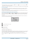
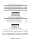
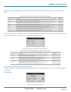
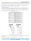
Factory>Group>Group Status (Screen 8) provides an overview of the current duty status for all the A/C units combined in the
group.
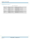
Table 4-23. Factory>Group>Group Status (Screen 8) parameters.
Display Description Description Variables Default
Running Display indicates how many units in the group are currently operating. 0 to 8 0
Active Display indicates how many units in the group are currently active. 0 to 8
0
Standby Display indicates how many units in the group are currently in standby. 0 to 8
0
Assist Display indicates how many units in the group are currently operating in the capacity assist mode. 0 to 8
0
Online Display indicates how many units in the group are currently available to operate. 0 to 8
0
Out of Service Display indicates how many units in the group are not available to operate.
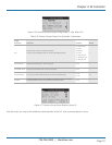
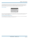
The final step to configure a workgroup is to access the Service>Options>Group Setup screens used to configure parameters that
apply to how individual A/C units interact in the workgroup (see Section 4.6.2.7).
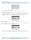
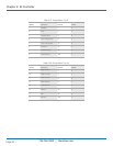
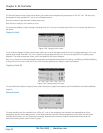
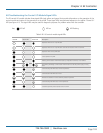
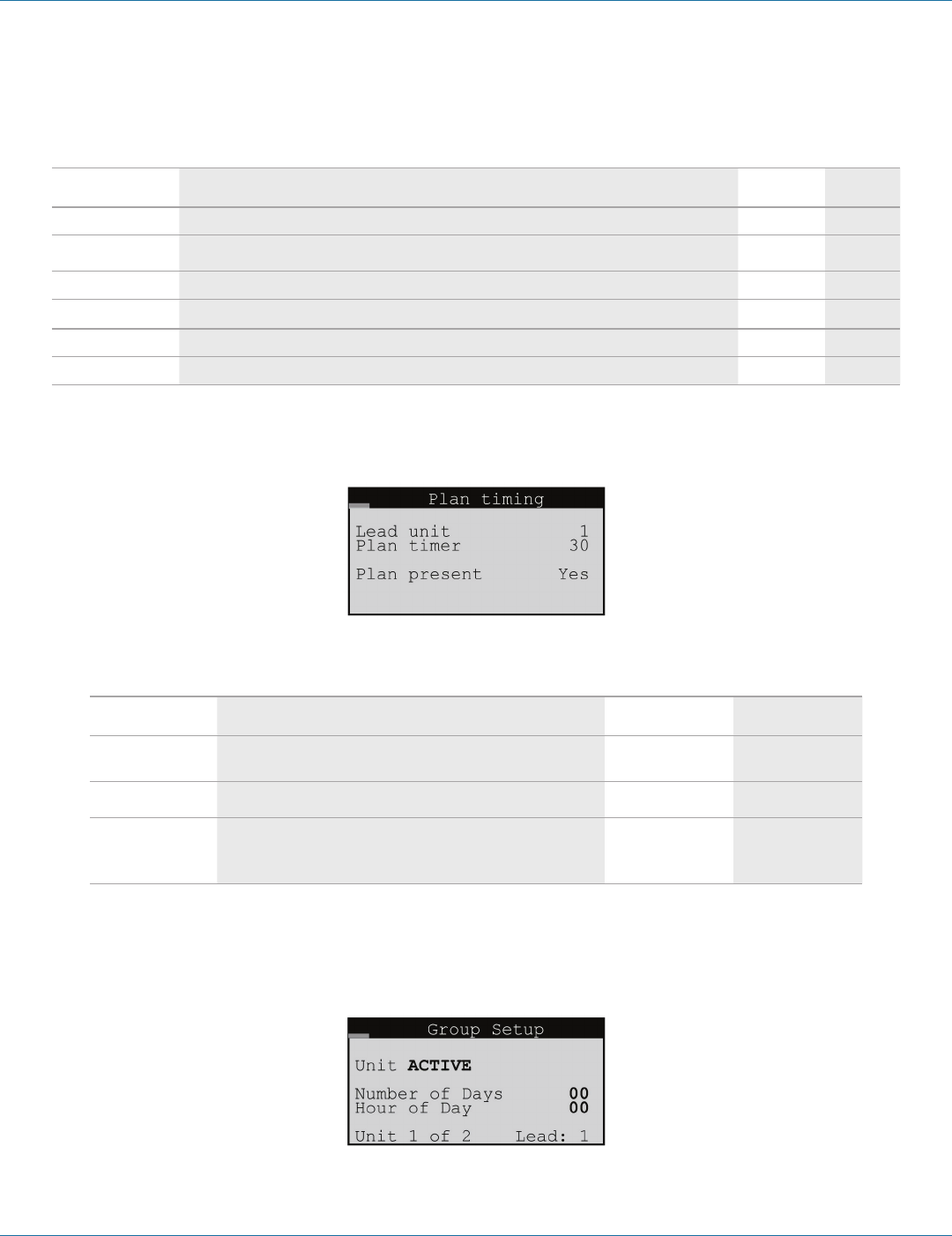
Figure 4-84. Factory>Group>Plan timing (Screen 9).
Table 4-24. Factory>Group>Plan timing (Screen 9) parameters.
Display Description Description Variables Default
Lead unit Display indicates which unit is currently the lead.
0 to 8
0
Plan timer
Display indicates the time delay (in seconds) between the detection of
a communication failure and the annunciation of a Comm alarm.
0 to 60 30
pLAN present Display indicates if a pLAN is detected by the controller.
0 = No
1 = Yes
No
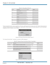
4.6.2.7 Service>Options>Group Menu Screens
Accessed in the Service menu, the Service>Options>Group Setup screens only appear if two or more units are wired together as
a workgroup.
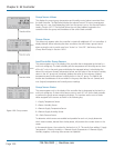
Group Setup
Figure 4-85. Group setup screen.