


724-746-5500 | blackbox.com
724-746-5500 | blackbox.com
Page 33
Chapter 2: Installation
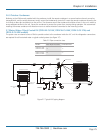
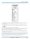
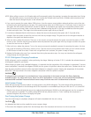
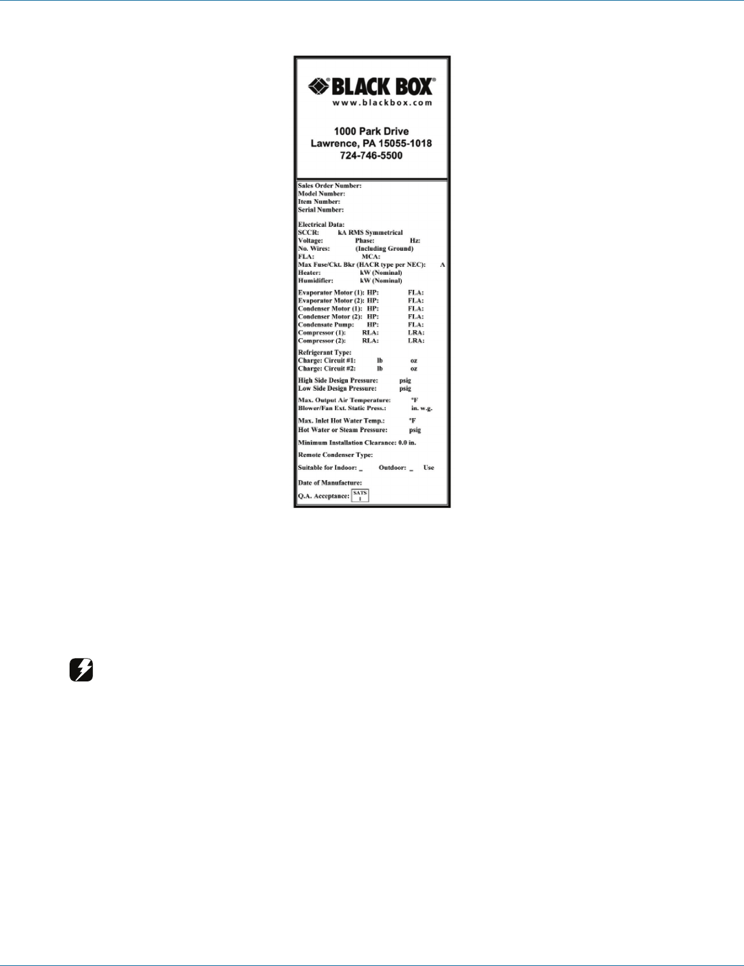
Figure 2-12. Sample nameplate.
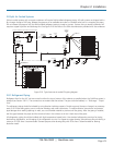
The unit is provided with terminals for all required field wiring. Refer to the electrical drawing supplied with the unit for all power
and control field wiring. It is important to identify the options that were purchased with the unit to confirm which field
connections are required.
NOTE: All wiring must conform to local and national electrical code requirements. Use of copper conductors only is required.
Wiring terminations may become loose during transit of the equipment; verify that all wiring terminations are secure.
WARNING
Verify power is turned off before making connections to the equipment.
It is important to verify that the main power supply coincides with the voltage, phase, and frequency information specified on the
system nameplate. The supply voltage measured at the unit must be within ±10% of the voltage specified on the system
nameplate, except for 208/230V single-phase units that have a different tolerance listed below.
A main distribution panel must be provided with a manual fused disconnect switch or HACR-type circuit breaker per local and
national electrical codes for service to the equipment. Do not mount a customer-supplied manual fused disconnect switch or
HACR-type circuit breaker to the surface of the unit.
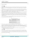
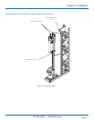
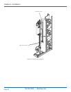
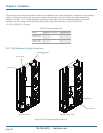
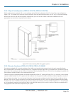
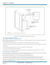
The unit has main power and control pilot holes for connection of the field-wiring conduit. These pilot holes are located on the
Cold Row unit based on the configuration. The pilot holes are located in the top of the cabinet or in the floor of the cabinet. A
label stating “MAIN POWER INPUT” is placed nearby. See the installation drawing provided with your unit for pilot hole locations.
Terminate the main power wires at the line side of the service disconnect switch, located within the electric box. A
separate equipment ground lug is provided within the electrical box for termination of the ground wire.