


724-746-5500 | blackbox.com
Page 88
724-746-5500 | blackbox.com
Chapter 4: E2 Controller
4.6.2.2 Configure the Controller (I/O Board) pLAN Address
Immediately after turning power back on, press and hold the Alarm and the up-arrow keys simultaneously for 10 to 15
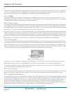
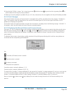
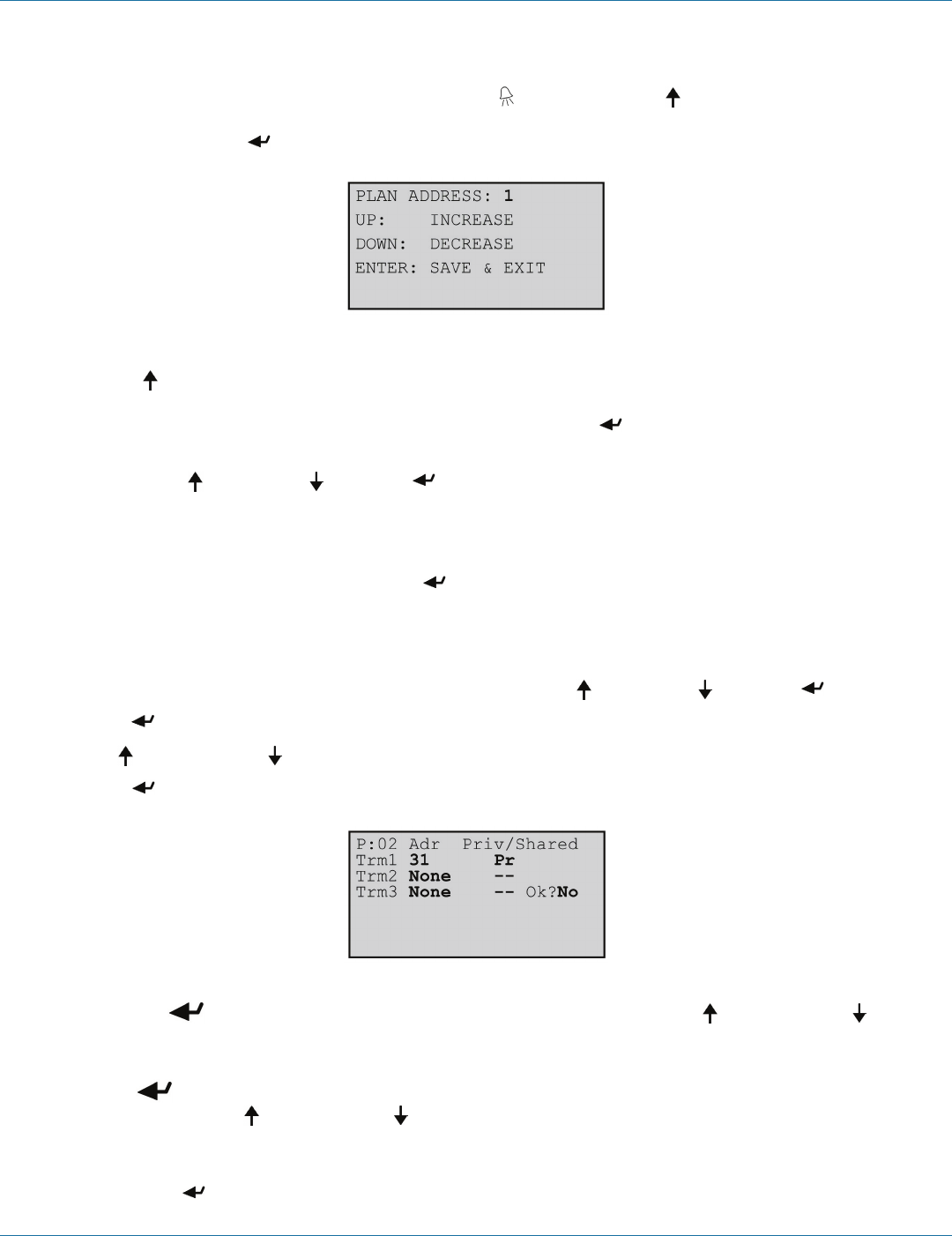
seconds. First you will see a display message “self test please wait” then the pLAN Address Configuration screen shown below
will appear. Don’t press the Enter key; the cursor is already in the modifiable field.
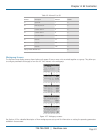
Figure 4-70. pLAN Address screen.
Press the up-arrow key to set the pLAN address (1–8) for the controller (I/O board). The pLAN Address 1 is already assigned by
default to the first (lead) controller in the group. Address 2 is to be assigned to the first controller added to the group (Address 3
is to be assigned to the second controller added and so on). Then press the Enter key to confirm your selection. A message
“NO LINK” will appear.
Next, press the up-arrow , down-arrow , and Enter keys simultaneously. Reconfigure the terminal address following the
steps in Section 4.6.2 again. This time set the terminal address to match the corresponding controller (I/O board) address. If the
controller is assigned Address 2, then the corresponding terminal address should be set to 31 as shown in Table 4-11. If the next
controller is assigned Address 3, the corresponding terminal should be set to 30.
After setting the correct terminal address, press the Enter key once to confirm your selection. A message “NO LINK” will
appear. At this point, the terminal has been set with the correct address for the controller, and the controller has been set for the
terminal—but now they need to be assigned to each other.
4.6.2.3 Assign the Terminal to the Controller
1. Access the Terminal Address Configuration screen again using the up-arrow , down-arrow , and Enter keys.
2. Press the Enter key until the cursor moves to the field “I/O board address:__”.
3. Using the up and down-arrow keys, enter the address (1–8) for the controller I/O board.
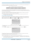
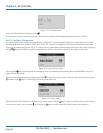
4. Press the Enter key twice to display the Terminal Configuration screen shown below.
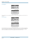
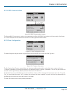
Figure 4-71. Terminal Configuration screen.
5. Here, too, the Enter key moves the cursor from one field to the next, and the up-arrow and down-arrow keys
change the value of the current field. The field “P:0_” depicts the pLAN address (1–8) assigned to the I/O board. In the
example shown, the controller has been assigned address 2.
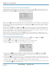
6. Press the Enter ( ) key to move to the field “Trm1 xx”. The field represents the address of the terminal associated with the
controller. Using the up-arrow and down-arrow keys, enter the address (25–32) of the terminal assigned to the controller
(I/O board). In Figure 4-41, Address 31 has been entered for the first A/C unit added to the group.
7. The Priv/Shared column indicates the type of terminal. The workgroup is setup using private terminals. Do not change the value
(“Pr”). Press the Enter key to move to the last field.