724-746-5500 | blackbox.com
Page 32
724-746-5500 | blackbox.com
Chapter 4: Configuring the Hardened Serial Server
4.7.3 Setting Up Virtual COM (VCOM) Operation
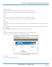
When the Network Protocol is set to VCOM (Virtual COM Port), the Hardened Serial Server communicates over the network with
a PC, acting as a remote COM port for the computer.
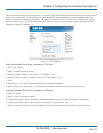
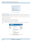
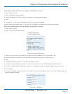
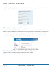
Figure 4-13. VCOM configuration.
NOTE: Both the Hardened Serial Server and the computer must be configured for VCOM operation. To set up a virtual COM port
on the computer, refer to ”Adding Virtual COM Ports” (Section 4.10).
1. To enable VCOM operation, select “VCOM” protocol.
2. Click “Save.”
4.7.4 Setting Up Paired Mode Operation
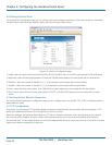
Paired Mode enables two Hardened Serial Servers to operate across the network like a “wire replacement” between two serial
devices. (Paired Mode is also called serial tunneling.) Serial devices connected to serial servers on each end of the link can
communicate as it they were connected by a serial cable.
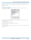
For Paired Mode to work one Hardened Serial Server must be configured “to initiate connections (client)” and the other must be
configured “to wait for connections (server).”
The Hardened Serial Server configured as the client initiates the connection. You must set up the IP address and port number of
the server that you want the client (Hardened Serial Server) to communicate with. You also select whether you want the
Hardened Serial Server to connect at power up or only when it receives data from the device connected to its serial port.
The Hardened Serial Server configured as a server waits for a connection to be initiated by the remote client. You must set up the
TCP port number on which it will listen for connections and set the maximum (up to four) number of simultaneous connections it
will accept. The maximum number of connections should be set to at least two (2) to allow the unit to recover if the connection is
terminated abnormally. You can filter the connections it will accept based on specific IP addresses or ranges of IP addresses that
you specify.
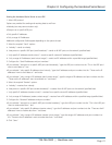
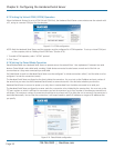
Figure 4-14. Paired Mode configuration.


