


724-746-5500 | blackbox.com Page 13
Chapter 2: Overview
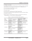
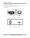
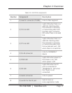
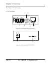
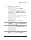
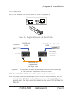
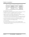
Table 2-3. LGC202A components.
Number Component Description
1
(1) dual SC connector
(TX/RX)
Links to fiber segment
2 (1) FX Link LED
Lights ON when there is a valid link.
Flashing when the converter is
receiving or transmitting data from
the fiber optic connector. OFF
when there is no valid link.
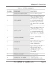
3 (1) TP Link LED
Lights ON when there is a valid link.
Flashing when the converter is
receiving or transmitting data from
the twisted-pair port. OFF when
there is no valid link.
4 (1) RJ-45 connector Links to 1000BASE-T device
5 (1) PWR LED
Lights ON when power to the
chassis is on; OFF when power is
off.
6 (1) RX LED
Lights ON when the TP port is con-
nected to 1000BASE-TX. OFF when
the TP port is not connected.
7 (1) barrel connector Links to power
8
(1) switch for the FX
port
Selects Force or
Auto-negotiation mode
*See Table 5-1 for LED functions.