


24
M
ANAGING
R
EDUNDANT
CONNECTIONS
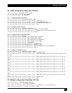
24.1 Trunk Group/Failover
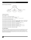
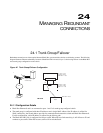
Redundant connections are often required between Black Box systems and the switches to which they connect. The following
diagram illustrates Ethernet redundancy between a Black Box LR1114A and a Layer 3 switch using failover on the Black Box
and a trunk group configuration on the switch.
Figure 42 Trunk Group/Failover Configuration
24.1.1Configuration Details
Black Box Ethernet 0 and 1 are connected to ports 1 and 2 of a trunk group configured switch.
The trunk group is configured with three IP addresses and a single MAC address. One IP address is utilized for
WAN connectivity; the second address provides for communication between the switch and Black Box Ethernet 0.
For this configuration, a third IP address is utilized for the failover path.
The Black Box LR1114A is configured for failover on E0. When E0 loses link conectivity, it will failover to E1 and
continue to pass traffic. When E0 recovers, traffic will be switched back.
WAN
T
asman 1400
Router
Layer 3 Switch
w/Trunk Group
Trunk Group
E1
E2
E0 E1
Failover
Tasman 1400
Layer 3 Switch
Router
E1: 199.1.1.1/30
E2: 199.1.1.5/30
WAN: 200.1.1.1/30
E0: 199.1.1.2/30
E1: 199.1.1.6/30
WAN: 10.1.1.1/30
WAN: 200.1.1.2/3
0
LR1114A