


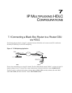

7
IP M
ULTIPLEXING
HDLC
C
ONFIGURATIONS
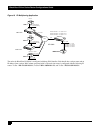
7.1Connecting a Black Box Router to a Router/CSU
via HDLC
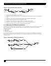
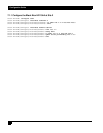
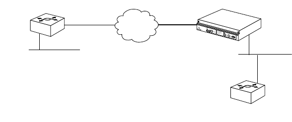
The following diagram details a single T1 connection between a Black Box and a remote router/CSU combination.
Secondary IP addressing is used for IP multiplexing.
Figure 15 IP Multiplexing Application
The two sites communicate over a single T1 channel. The Site 2 WAN bundle, named “ToSite1”, consists of a single T1
channel coming in via a CT3 circuit. Site 1 router's default route is directed to the Site 2 router: 0.0.0.0/0 10.1.1.1
The Site 2 router is configured with: primary ethernet address: 129.1.1.1/24, secondary ethernet addr on the WAN
subnet: 10.1.1.1/24, and route to the Site 1 router: 192.5.75.0/24 10.1.1.3.
1
92.5.75.0/24
192.5.75.1/24
Router/
T1 CSU
10.1.1.3/24
T1
CT3
Tasman 6300
10.1.1.2/24
Telco
Router
SITE 1
SITE 2
129.1.1.2/24
Primary: 129.1.1.1/24
Secondary: 10.1.1.1/24
LR1104A