25
WAN I
NTERFACE
C
ONFIGURATIONS
25.1 T1 Interface Configuration
Black Box systems are available with T1 WAN interfaces. Consult the Black Box System Installation Guide for details
on WAN interface types, cabling, and pinouts.
This document outlines the configuration of module parameters (Layer 1) and, to a lesser degree, the configuration of
bundle parameters (Layer 2). The bundle configuration examples demonstrate linking of physical interfaces (modules)
to logical interfaces (bundles). Module configuration occurs within the configure module tree of the Black Box CLI,
and bundle configuration occurs within the configure interface bundle tree.
Black Box T1 interfaces support logical interfaces made up of fractional T1, single T1, and multi-link T1connections.
25.1.1Module Configuration
25.1.1.1 T1
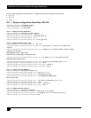
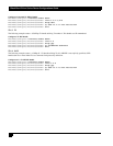
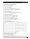
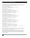
The following example configures the operational and descriptive parameters for T1 number 6.
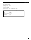
Configure T1 Parameters
Blackbox/configure> module t1 6
Blackbox/configure/module/t1> circuitId X1234567890
Blackbox/configure/module/t1> contactInfo George_Anderson
Blackbox/configure/module/t1> description T1_to_Troy
Blackbox/configure/module/t1> framing esf
Blackbox/configure/module/t1> linecode b8zs
Blackbox/configure/module/t1> clock_source line
Blackbox/configure/module/t1> exit
25.1.2 Bundle Configuration
Configuration of an interface bundle is required for use of any of the Black Box system WAN interfaces. Multiple physical
interfaces may be linked to a single interface bundle; multi-link protocols, including MLPPP and Multilink Frame Relay,
make use of NxT1 interfaces to create single logical interfaces.
The interface bundle specifies the physical connection(s) to be linked, an encapsulation protocol (Layer 2) and, optionally,
Layer 3 parameters.
25.1.2.1 Fractional T1
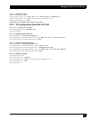
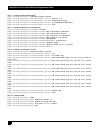
The following example creates a 384 Kbps fractional T1 bundle utilizing DS0s 1-3 and 8-10 of T1 number 3.


